Control apparatus for internal combustion engine
- Summary
- Abstract
- Description
- Claims
- Application Information
AI Technical Summary
Benefits of technology
Problems solved by technology
Method used
Image
Examples
embodiment 1
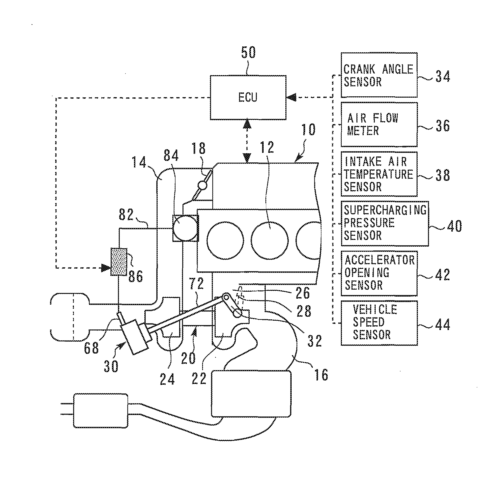
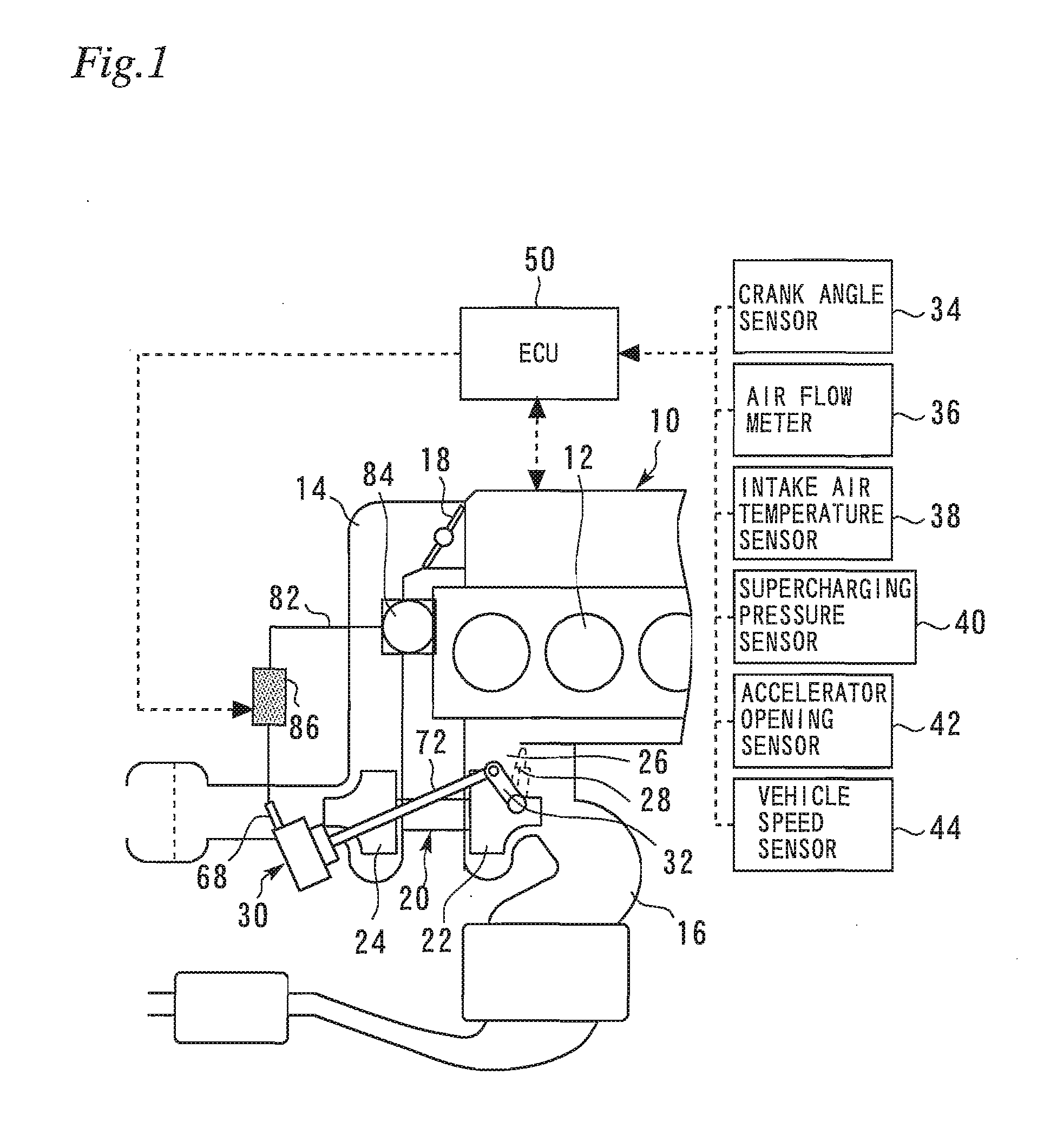
[0062]FIG. 1 is a diagram for illustrating a system configuration according to an embodiment 1 of the present invention. As shown in FIG. 1, a system according to this embodiment has an internal combustion engine 10 (referred to simply as an engine 10 hereinafter) mounted in a vehicle or the like. In each cylinder 12 of the engine 10, a fuel injector, an ignition plug, an intake air valve, an exhaust air valve and the like are provided. The engine 10 further has an intake path 14 through which an intake air is fed into each cylinder 12 and an exhaust path 16 through which an exhaust gas is discharged from each cylinder 12. The intake path 14 is provided with a throttle valve 18 that regulates the amount of intake air.
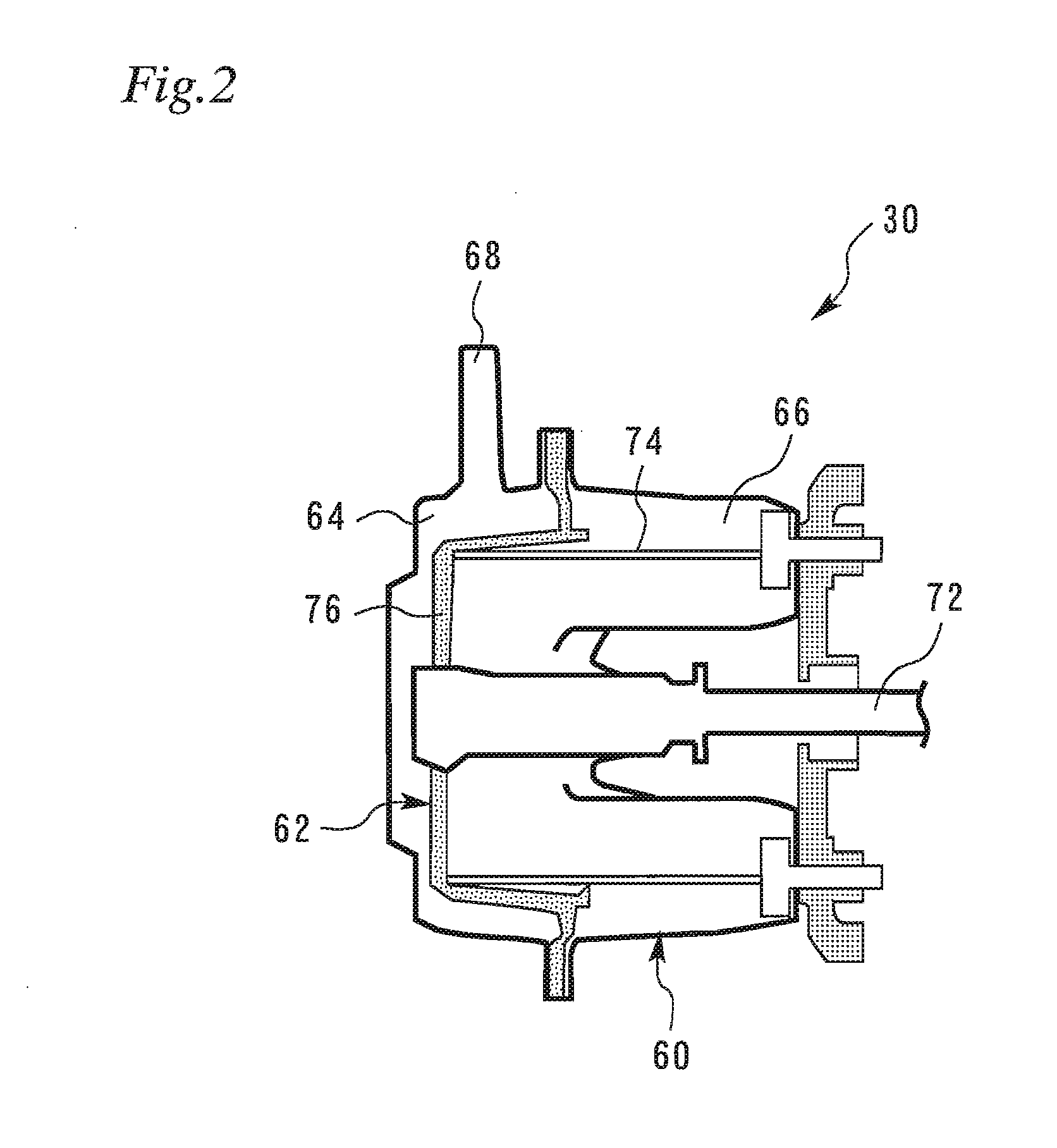
[0063]The engine 10 further has a turbocharger 20 that supercharges the intake air by using the energy of the exhaust gas. The turbocharger 20 has a turbine 22 provided in the exhaust path 16 and a compressor 24 provided in the intake path 14. The turbine 22 is rotated ...
embodiment 2
[0111]Next, an embodiment 2 of the present invention will be described with reference to FIG. 10. The description will be focused mainly on differences from the embodiment 1 described above, and description of commonalties with the embodiment 1 will be simplified or omitted. The hardware configuration according to this embodiment is the same as that according to the embodiment 1, and thus, description thereof will be omitted.
[0112]In the case where the diaphragm type actuator 30 of the positive pressure type is used, when the waist gate valve 28 is open, a positive pressure is applied from the positive pressure source to the diaphragm type actuator 30. To close the waist gate valve 28 in this state, the positive pressure has to be released to decrease the diaphragm pressure. The higher the positive pressure acting in the state where the waist gate valve 28 is open, the longer the time required to reduce the diaphragm pressure to the value at which the waist gate valve 28 closes. The...
embodiment 3
[0122]Next, an embodiment 3 of the present invention will be described with reference to FIGS. 11 and 12. The description will be focused mainly on differences from the embodiments described above, and description of commonalties with the embodiments will be simplified or omitted. The hardware configuration according to this embodiment is the same as that according to the embodiments in other respects than described below, and thus, description thereof will be omitted. The embodiment 3 described below is a combination of the embodiments 1 and 2 described above.
[0123]FIG. 11 is a longitudinal cross-sectional view of a diaphragm type actuator according to the embodiment 3 of the present invention. As shown in FIG. 11, in the low pressure chamber 66 of the diaphragm type actuator 30 according to this embodiment, a second coil spring 78 is disposed in addition to a first coil spring 74. The first coil spring 74 and the second coil spring 78 push the diaphragm 62 toward the high pressure...
PUM
 Abstract
Description
Claims
Application Information
 - R&D
- Intellectual Property
- Life Sciences
- Materials
- Tech Scout
- Unparalleled Data Quality
- Higher Quality Content
- 60% Fewer Hallucinations
Browse by: Latest US Patents, China's latest patents, Technical Efficacy Thesaurus, Application Domain, Technology Topic, Popular Technical Reports.
© 2025 PatSnap. All rights reserved.Legal|Privacy policy|Modern Slavery Act Transparency Statement|Sitemap|About US| Contact US: help@patsnap.com


