Radiation monitoring apparatus, systems, and methods

Inactive Publication Date: 2006-03-09
HALLIBURTON ENERGY SERVICES INC
View PDF10 Cites 43 Cited by
  • Summary
  • Abstract
  • Description
  • Claims
  • Application Information

AI Technical Summary

Benefits of technology

[0036] Such embodiments of the inventive subject matter may be referred to herein, individually and/or collectively, by the term “invention” merely for convenience and without intending to voluntarily limit the scope of this application to any single invention or inventive concept if more than one is in fact disclosed. Thus, although specific embodiments have been illustrated and described herein, it shoul

Problems solved by technology

Radiation detection mechanisms, perhaps used to determine the unauthorized use of certain materials, may include rather fragile devices, such as Geiger-Muller tubes.
These de

Method used


Image

  • Radiation monitoring apparatus, systems, and methods
  • Radiation monitoring apparatus, systems, and methods
  • Radiation monitoring apparatus, systems, and methods

Examples


Embodiment Construction

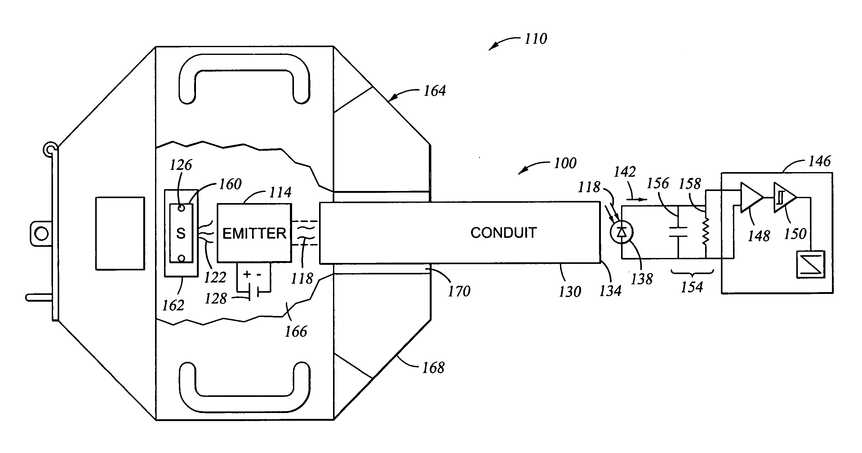
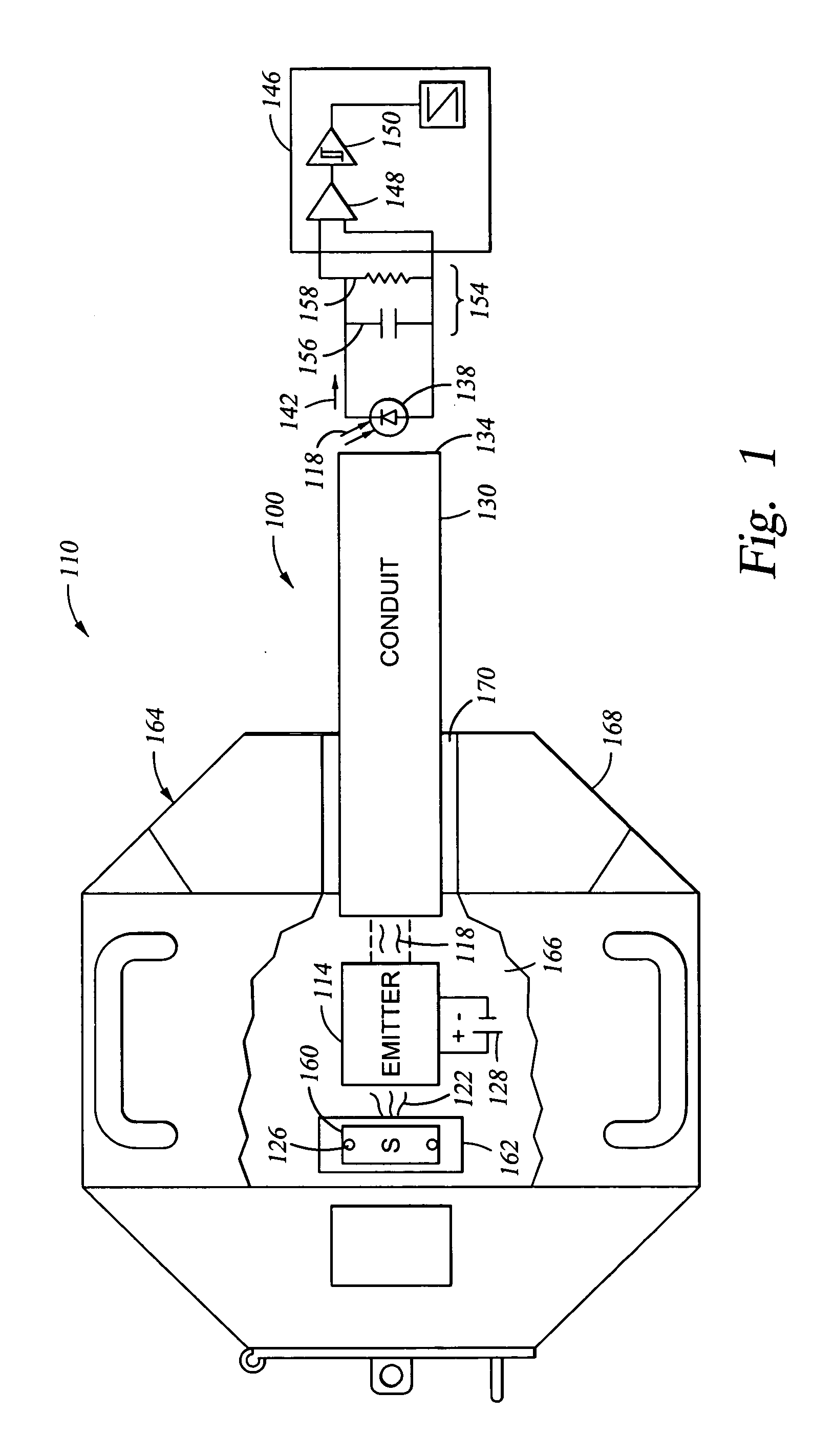
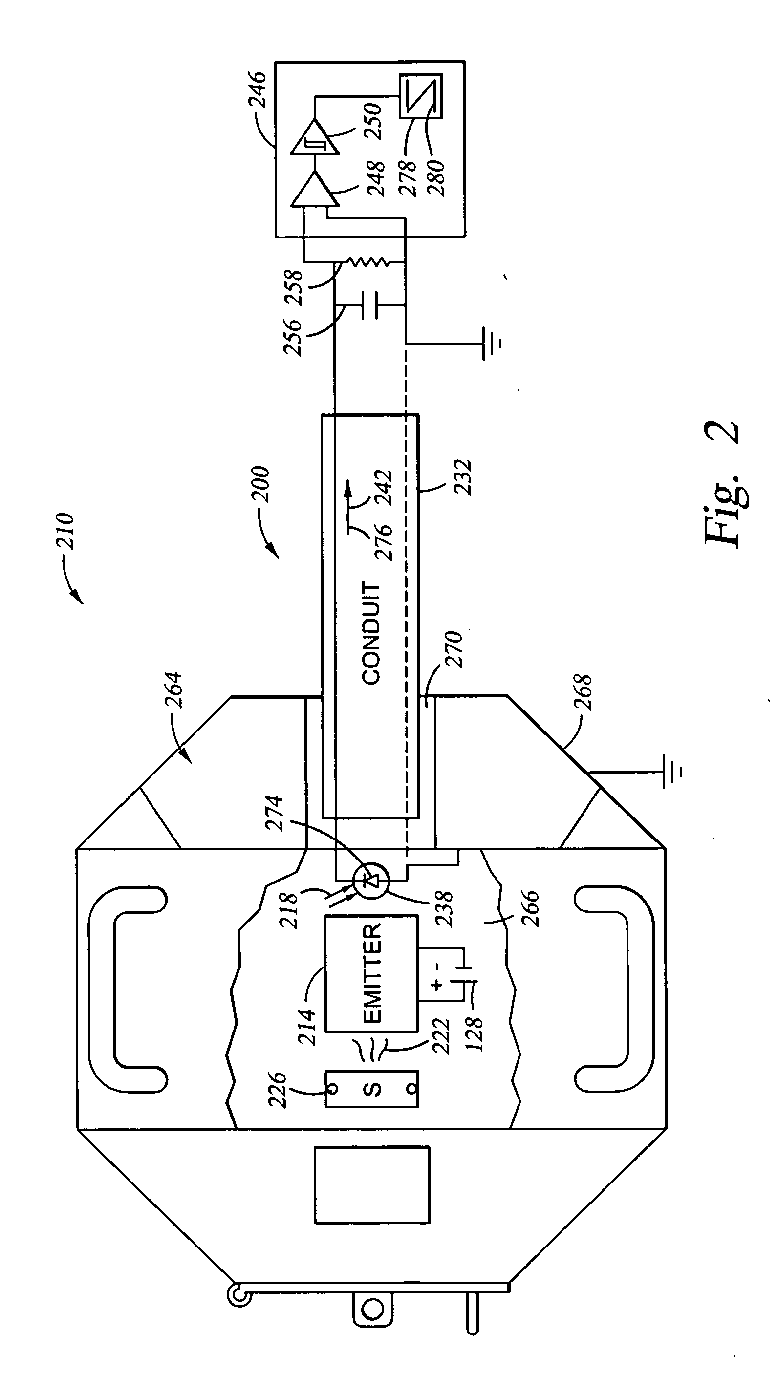
[0006] In some embodiments of the invention, the challenges described above may be addressed by taking advantage of photon emission that can occur in response to radiation, perhaps using an unpowered detector. For example, a radiation container, such as a radiation source transport pig, may contain a source of radiation and a detector (e.g., a scintillating crystal). The crystal may emit photons in the visible light region responsive to radiation, and an optical fiber can be used to transport the photons from the interior of the container to the exterior, where the photons can be viewed, or received for further processing. In some embodiments, the optical fiber may include a doped portion that responds to radiation by emitting photons that can be transported along the remainder of the fiber.

[0007] It should be noted that adopting the approach disclosed herein may present several advantages. For example, warning lights included on the dashboard of an automobile, while depicting a ch...


PUM


Abstract

In some embodiments, radiation may be detected by emitting photons responsive to the radiation at a first location, and transporting the photons to provide an indication of photon presence at the second location. In some embodiments, operations may include generating a current at a first location by receiving radiation from a source at a semiconductor junction, and transporting the current to provide an indication of source presence at the second location.

Description

TECHNICAL FIELD [0001] Various embodiments described herein relate to monitoring radiation generally, including apparatus, systems, and methods that can be used to detect and indicate the presence of radiation. BACKGROUND INFORMATION [0002] Radiation detection mechanisms, perhaps used to determine the unauthorized use of certain materials, may include rather fragile devices, such as Geiger-Muller tubes. These devices may not readily survive rough handling, and may utilize relatively complex electrical circuitry to process the signals obtained therefrom (e.g., accumulating counters).BRIEF DESCRIPTION OF THE DRAWINGS [0003]FIG. 1 is a block diagram of apparatus and systems according to various embodiments of the invention; [0004]FIG. 2 is a block diagram of additional example embodiments of the invention; and [0005]FIGS. 3A and 3B are flow diagrams illustrating several methods according to various embodiments of the invention.DETAILED DESCRIPTION [0006] In some embodiments of the inve...

Claims


Application Information

Patent Timeline
IPC IPC(8): G01V5/08
CPCG01V5/08G01T1/20
Inventor RAO, M. VIKRAMRODNEY, PAUL F.
Owner HALLIBURTON ENERGY SERVICES INC
Why Eureka
Try Eureka