
Flange adapter

a technology of adapters and flanges, which is applied in the direction of flange joints, mechanical equipment, functional valve types, etc., can solve the problems of reducing reducing the efficiency of flanges, and requiring strict maintenance and inspection for proper performance and replacement, so as to achieve the effect of less costly and increasing the standardization of safety heads

Active Publication Date: 2006-03-09
BS&B SAFETY SYST LTD
View PDF11 Cites 30 Cited by
  • Summary
  • Abstract
  • Description
  • Claims
  • Application Information

AI Technical Summary

Benefits of technology

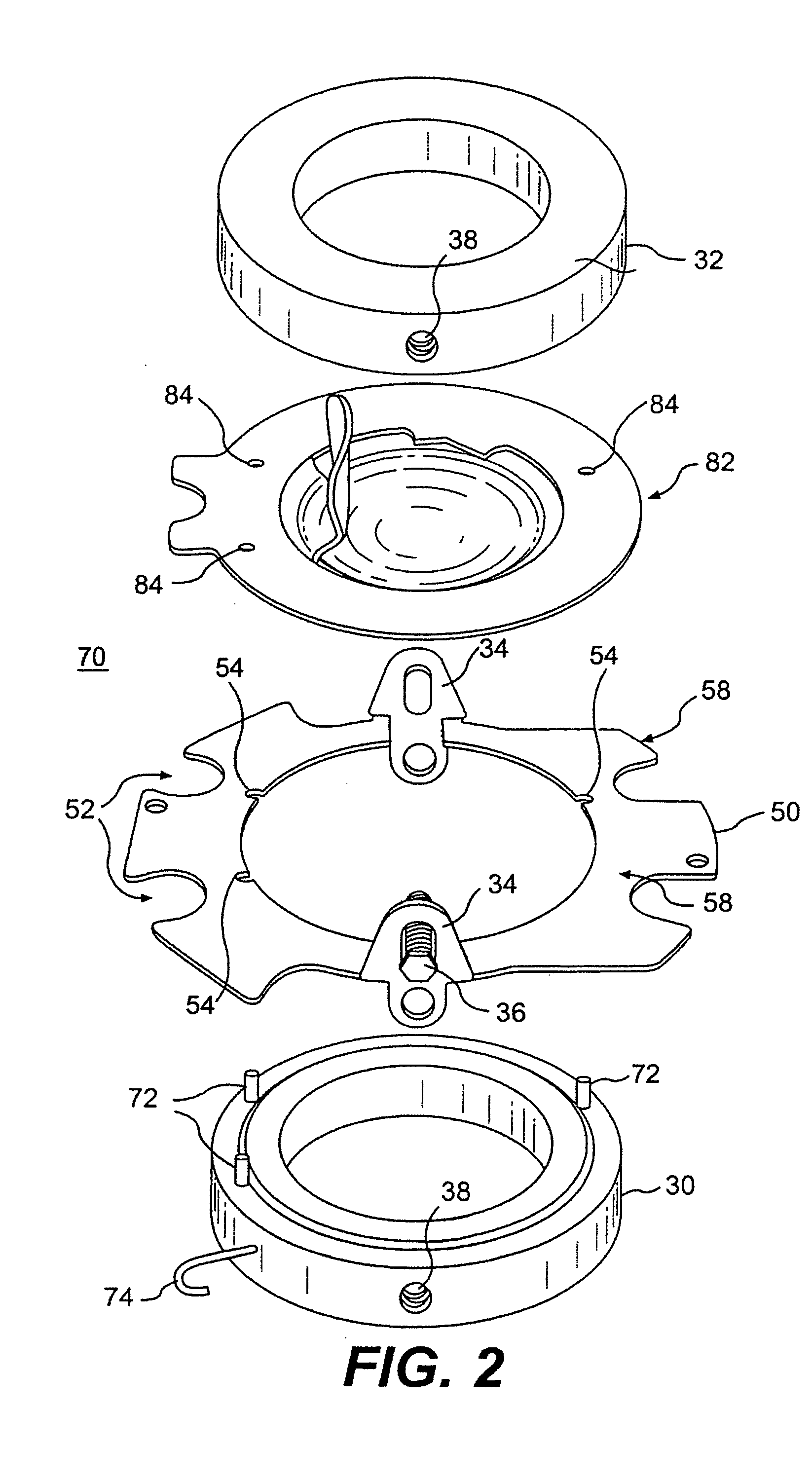
[0011] A flange adapter is provided for positioning an insert device within a pressurized fluid system. The flange adaptor assembly includes a pressure containing boundary and a flange adapter configured to be selectively connected to the pressure containing boundary. The adapter is configured to interchangeably fit a plurality of flange standards for the same nominal size. The adapter may also interchangeably fit a plurality of pressure ratings for the same nominal size. The flange adapter may be manufactured separate from the pressure containing boundary to allow for using less costly material and to increase standardization of safety heads. Alternatively, the flange adapter may be formed integral with the underlying insert device without the use of a separate pressure containing boundary. Certain embodiments of the invention provide for a specific shape of the recesses of the adapter that mate with the bolts to allow for removal of an assembly from within companion pipe flanges without removal of all of the bolts. In addition, the present invention is directed to a gasket design configured to interchangeably fit a plurality of flange standards for the same nominal size. The gasket may also interchangeably fit a plurality of pressure ratings for the same nominal size.

Problems solved by technology

For example, a rupture disk will vent fluid from the system when the pressure in the system reaches an unsafe level.
A number of emergency conditions, including fire and system failure, can create dangerous pressure levels, which require immediate relief to preserve the safety of the system.
The size and shape of the opening created when the disk bursts is a limiting factor on the rate at which fluid can escape the system.
Conversely, where an insert device is positioned in an off-center manner, the velocity head loss over this smaller opening will create a larger pressure drop that may create an undesirable situation.
Insert devices and gaskets placed within a pressurized fluid system often require strict maintenance and inspection for proper performance and replacement.
Devices inserted within pressurized fluid systems often are cumbersome to remove from within companion bolted flange members.

Method used


Image

  • Flange adapter
  • Flange adapter
  • Flange adapter

Examples


Embodiment Construction

[0025] Reference will now be made in detail to the present exemplary embodiments of the invention, examples of which are illustrated in the accompanying drawings. Wherever possible, the same reference numbers will be used throughout the drawings to refer to the same or like parts.

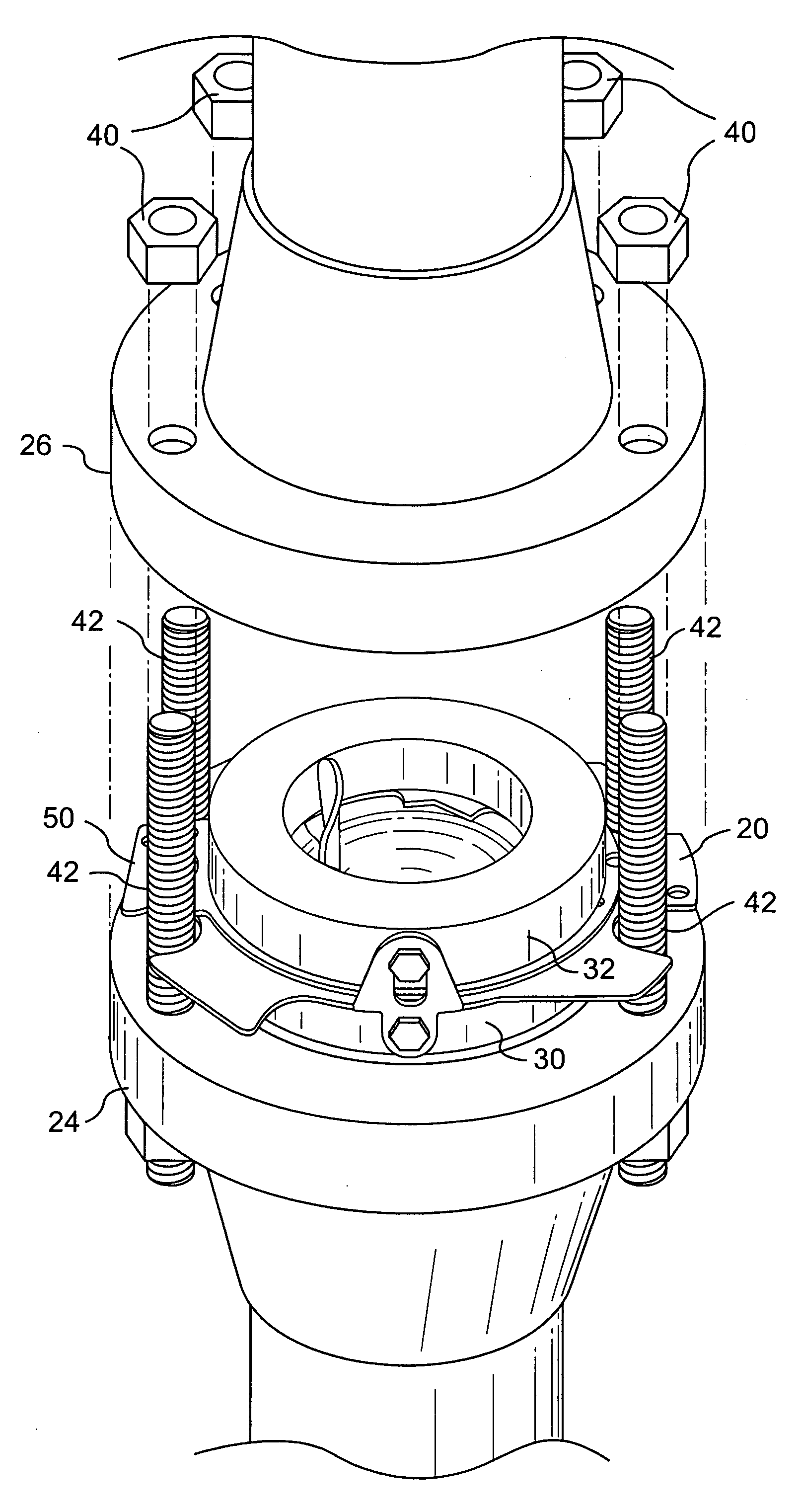
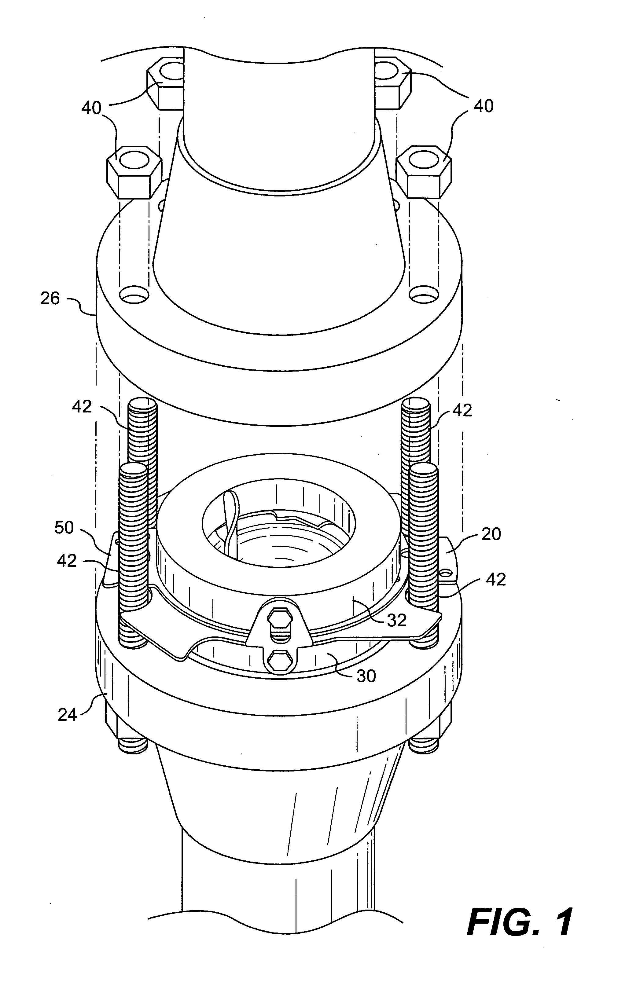
[0026]FIG. 1 depicts a safety head assembly, generally represented by number 20, installed between companion bolted flange members, 24, 26. Inlet pipe flange member 24 and outlet pipe flange member 26 will connect the pressure relief assembly within the flow path of a pressurized fluid system. The example of FIG. 1 shows safety head assembly, including an inlet safety head member 30 and an outlet safety head member 32. The safety head assembly 20 may act as a holder or support member for any number of insert devices for placement within a pressurized fluid system. The safety head assembly 20 is installed into the pressurized fluid system by means of compression between inlet pipe flange 24 and outlet pipe ...


PUM


Abstract

A flange adapter is provided for positioning an insert device within a pressurized fluid system. A flange adapter assembly includes a pressure containing boundary and a flange adapter configured to be selectively connected to the pressure containing boundary. The adapter is configured to interchangeably fit a plurality of flange standards for the same nominal size. The adapter may also interchangeably fit a plurality of pressure ratings for the same nominal size. The flange adapter may be manufactured separate from the pressure containing boundary to allow for utilizing less costly material and to increase standardization of safety heads. The present invention also includes a gasket design having multi-flange compatibility for use in pressurized fluid systems.

Description

FIELD OF THE INVENTION [0001] This invention relates to a coupling assembly for pressurized fluid systems, and more particularly to a flange adapter device for coupling within bolted flange members. BACKGROUND OF THE INVENTION [0002] In pressurized fluid systems or vessel components, pipe flanges are used to connect and seal adjoining pipe sections. In many systems containing pressurized fluids, additional insert devices are installed by means of an internal placement within the bolting pattern of exterior companion pipe flanges. These insert devices have a particular function depending upon the specific application of the underlying system. Representative examples of insert devices for placement within pressurized fluid systems include, but are not limited to, rupture disks, steam traps, check valves, and orifice plates. For example, a rupture disk will vent fluid from the system when the pressure in the system reaches an unsafe level. A number of emergency conditions, including fi...

Claims


Application Information

Patent Timeline
Patent Type & Authority Applications(United States)
IPC IPC(8): F16L23/00
CPCF16K17/16F16L23/16F16L23/003F16L23/006
Inventor BRAZIER, GEOFCULLINANE, DONALLTOMASKO, JOHN
Owner BS&B SAFETY SYST LTD
Learn More