Bumper with energy absorber forming useful features

a technology of bumpers and energy absorbers, which is applied in the field of bumpers, can solve the problems of difficult if not impossible to accurately shape the wall as desired, the towing strength of the towing structure is more limited than desired, and it is not as easy to form a hitch-supporting structur

a technology of bumpers and energy absorbers, which is applied in the field of bumpers, can solve the problems of difficult if not impossible to accurately shape the wall as desired, the towing strength of the towing structure is more limited than desired, and it is not as easy to form a hitch-supporting structur

US20060049650A1Inactive Publication Date: 2006-03-09SHAPE CORP

Image

  • Bumper with energy absorber forming useful features
  • Bumper with energy absorber forming useful features
  • Bumper with energy absorber forming useful features

Examples


Embodiment Construction

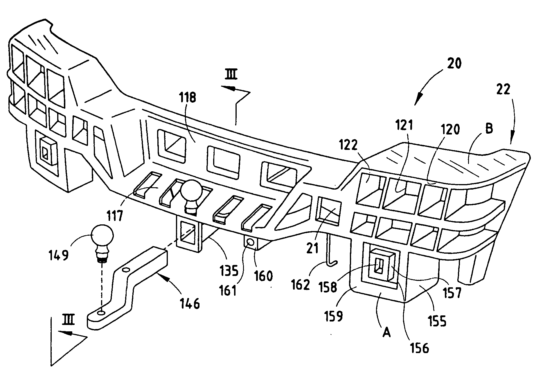
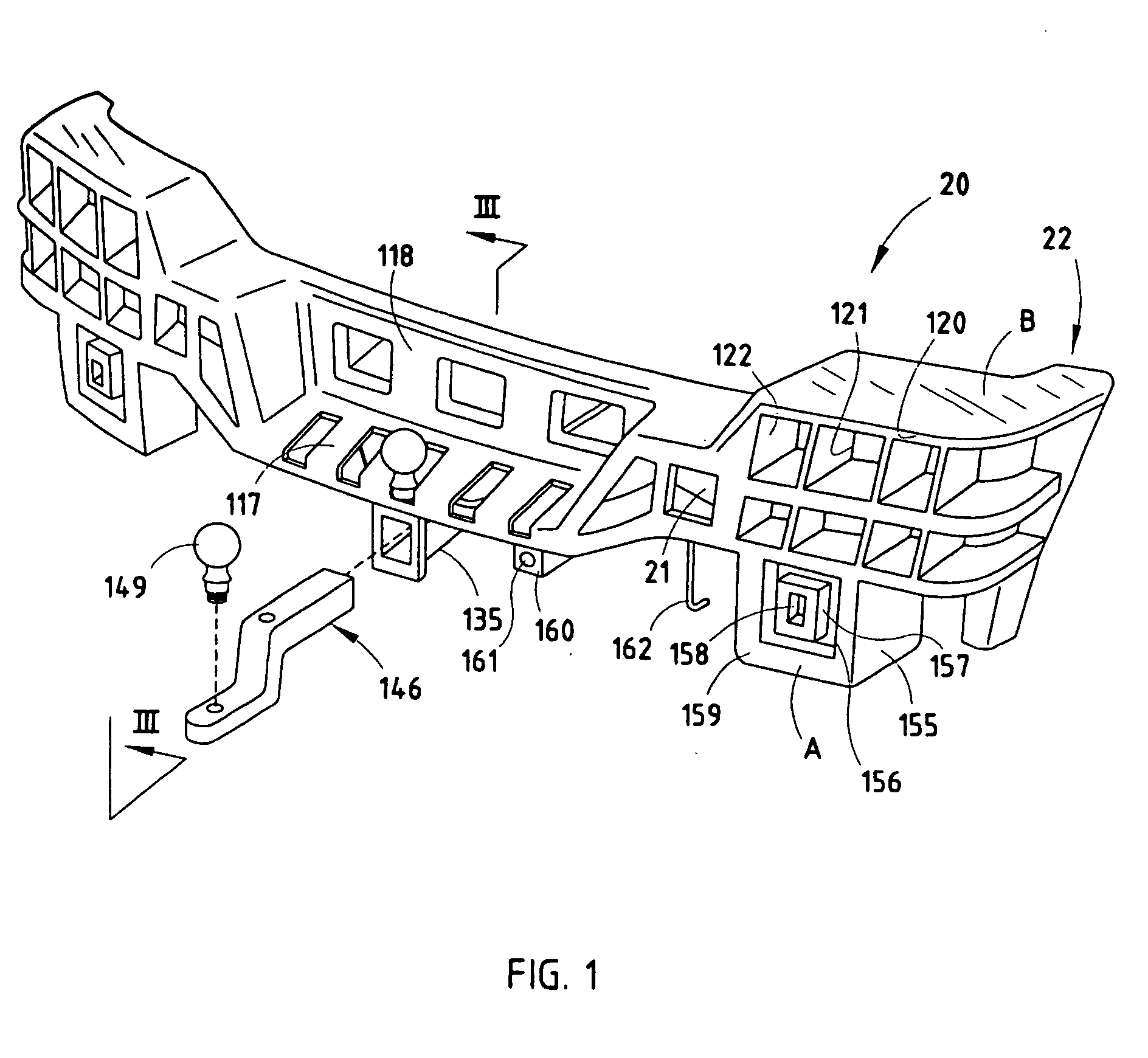
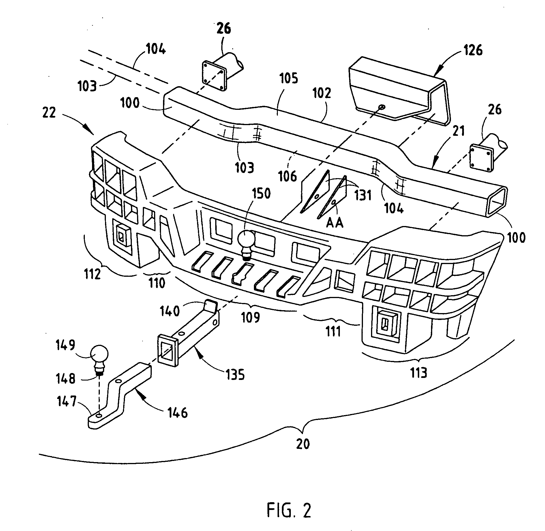
[0019] The bumper system 20 (FIGS. 1-2) is designed for use as a rear bumper for a vehicle, such as for a sport utility vehicle or truck. The bumper system 20 includes a beam 21 and an energy absorber 22 with a recess in its vehicle-facing surface for receiving the beam 21. A TPO plastic fascia (not specifically shown) covers the beam 21 and energy absorber 22 for aesthetics. The beam 21 may be rollformed or stamped and welded into a tubular shape, and / or hydroformed. It can have a rectangular, circular, or other cross section, but it is contemplated that the beam will be tubular for optimal torsional strength-to-weight ratio. The illustrated beam 21 is bent to include aligned opposing end sections 100 and 101, an offset middle section 102, and transition sections 103 and 104 that connect the end sections 100 and 101 to the middle section 102. The end sections 100 and 101 of the beam 21 are aligned and define a first centerline 103, and the middle section 102 defines a second center...


PUM


Abstract

A bumper system for a vehicle comprises a beam having a face and having mounts adapted for mounting to a vehicle frame, and an energy absorber engaging the face and having end sections located outboard of ends of the beam, the energy absorber being made of a structural engineering polymeric material and the end sections having flat top surfaces for forming steps outboard of the ends of the beam.

Description

CROSS REFERENCE TO RELATED APPLICATION [0001] This application is a continuation of application Ser. No. 10 / 957,228, filed Oct. 1, 2004 and entitled BUMPER WITH ENERGY ABSORBER FORMING USEFUL FEATURES, which is a divisional of application Ser. No. 10 / 726,169, filed Dec. 2, 2003 and entitled BUMPER WITH ENERGY ABSORBER FORMING USEFUL FEATURES, now U.S. Pat. No. 6,814,379, which is a divisional of application Ser. No. 10 / 294,124, filed Nov. 14, 2002, and entitled BUMPER WITH HITCH, now U.S. Pat. No. 6,709,036.BACKGROUND OF THE PRESENT INVENTION [0002] The present invention relates to bumpers having a hitch adapted to haul a trailer or the like, and also to bumpers having energy absorbers adapted to mount accessories and form steps. [0003] Rear bumpers of vehicles, especially utility vehicles and trucks, are often adapted with hitches to haul trailers. The hitch-supporting structure is often incorporated into the bumper in order to reduce components and to provide a more compact arrang...

Claims


Application Information

Patent Timeline
09 Mar 2006
Publication
US20060049650A1
IPC
B60R19/03; B60D1/14; B60D1/52; B60R19/18; B60R19/24; B60R19/48
CPC
B60D1/52; B60D1/56; B60D3/00; B60R19/18; B60R2019/1866; B60R19/48; B60R2019/1806; B60R2019/1813
Inventors
EVANS, DARIN