
Display apparatus and drive control method thereof

a technology of a display device and a control method, which is applied in the direction of instruments, computing, electric digital data processing, etc., can solve the problems of “leakage current between the tft source and the drain, liquid crystal deterioration, component failure, etc., and achieve favorable reduction of power consumption and eliminate wasteful power consumption

Inactive Publication Date: 2006-03-09
CASIO COMPUTER CO LTD
View PDF8 Cites 25 Cited by
  • Summary
  • Abstract
  • Description
  • Claims
  • Application Information

AI Technical Summary

Benefits of technology

[0028] The present invention comprises a plurality of display panels which perform an image display corresponding to a display signal. The present invention has the advantage in that when any one of the display panels is set in the non-display state, wasteful power consumption can be eliminated which results in a favorable reduction in power consumption.
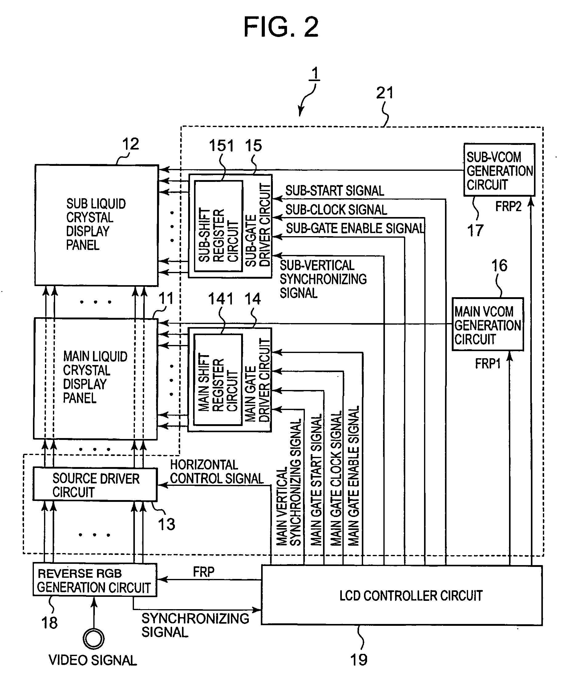
[0032] The control means controls the common electrode driver to perform polarity reversals of the common electrode signal to the display panel which has been set in the non-display state in each specific frame period which performs the refresh operation, lengthens a cycle of polarity reversals of the common electrode signal to the display panel which has been set in the display state in a plurality of frame periods that do not perform the refresh operation of the display panel which has been set in the non-display state more than a cycle of polarity reversals of the common electrode signal to the display panel which has been set in the display state in the specific frame period which performs the refresh operation, or controls to set the cycle of polarity reversals of the common electrode signal to the display panel which has been set in the display state as the same value in the plurality of frame periods that do not perform the refresh operation of the display panel which has been set in the non-display state.
[0036] The control means controls the common electrode driver to perform polarity reversals of the common electrode signal to the display panel which has been set in the non-display state in each of the specific frame period which performs the refresh operation, lengthens a cycle of polarity reversals of the common electrode signal to the display panel which has been set in the display state in a plurality of constant frame periods that do not perform the refresh operation of the display panel which has been set in the non-display state more than a cycle of polarity reversals of the common electrode signal to the display panel which has been set in the display state in the specific frame period which performs the refresh operation, or controls the cycle of polarity reversals of the common electrode signal to the display which has been set in the display state as the same value in the plurality of constant frame periods that do not perform the refresh operation of the display panel which has been set in the non-display state.

Problems solved by technology

However, when direct current is applied between these electrodes, it can induce overheating and seizing which causes the liquid crystal to deteriorate and ultimately component failure will occur.
However, even if the scanning lines of the main LCD panel are set in the non-scan state where the TFT is switched “OFF,” leakage current occurs between the TFT source and drain.
For this reason, even if the main LCD panel is set in the non-display state wherein the scanning lines are in the non-scan state, the electric field applied to the liquid crystal changes due to this leakage current and the non-display state is not satisfactorily sustainable.
Because of this, when the main LCD panel is set in a non-scan state, power consumption related to the reversal drive for the common voltage VCOM2 of the sub-LCD panel becomes a waste.
Accordingly, in a display apparatus having two LCD panels, even if it is the case where one of the LCD panels has been set in the non-display state, wasteful power consumption occurs related to the drive of the LCD panel side set in the non-display state.

Method used


Image

  • Display apparatus and drive control method thereof
  • Display apparatus and drive control method thereof
  • Display apparatus and drive control method thereof

Examples


Embodiment Construction

[0049] Hereinafter, the details of the display apparatus and associated drive method related to the present invention will be explained based on the preferred embodiments shown in the drawings.

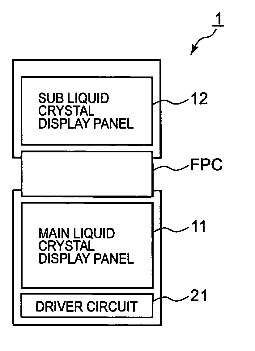
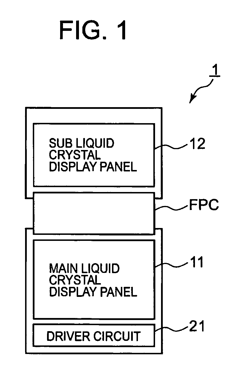
[0050] Also, hereinafter a display apparatus having two LCD panels with common signal lines (source lines) will be explained. Moreover, although the case explained below is configured so that one driver circuit which includes a source driver circuit, a gate driver circuit, etc. can be shared with two LCD panels, the display apparatus is not limited to this. For example, it is also effective to have a configuration in which one source driver circuit is shared with two LCD panels and a gate driver circuit is provided for exclusive us in each the LCD panels.

[0051] Additionally, in the following, although the two LCD panels have the same number of signal lines, the present invention is not restricted to this. For example, it is also possible to have the number of signal lines of one LCD panel be...


PUM


Abstract

A display apparatus which displays an image corresponding to a display signal comprising a plurality of display panels which have, respectively, a plurality of display pixels; and•• a control means which sets at least one display panel among the plurality of display panels in a display state and sets the plurality of display panels other than the at least one display panel in a non-display state, drives the display panel which has been set in the display state based on the display signal for each of a plurality of constant frame periods, and drives the display panel which has been set in the display state based on the display signal and performs a refresh operation of the display panel which has been set in the non-display state only in a specific frame period from the plurality of constant frame periods.

Description

CROSS-REFERENCE TO RELATED APPLICATION [0001] This application is based upon and claims the benefit of priority from the prior Japanese Patent Application No. 2004-262525, filed Sep. 9, 2004, the entire contents of which is incorporated herein by reference.BACKGROUND OF THE INVENTION [0002] 1. Field of the Invention [0003] The present invention relates to a display apparatus having a plurality of display panels and accompanying drive control method. [0004] 2. Description of the Related Art [0005] As the display panel in portable electronic apparatus, such as cellular phones, Personal Digital Assistant (PDAs), etc., a lot of display apparatuses have a liquid crystal display (hereinafter, denoted as “LCD”) panel with thin shape, light weight and low power consumption. In particular, many display apparatuses have a LCD panel of the active-matrix method which uses thin film transistors (TFTs) as the display panel. [0006] On the LCD panel of such display apparatuses, a plurality of scann...

Claims


Application Information

Patent Timeline
IPC IPC(8): G09G5/00
CPCG09G3/3614G09G3/3666G02F1/133G09G3/20G09G3/36
Inventor KAMIO, TOMOMI
Owner CASIO COMPUTER CO LTD
Learn More