Image recording apparatus

a recording apparatus and image technology, applied in the field of image recording apparatus, can solve the problems of inability to prevent a decrease in image quality, the like, and achieve the effects of preventing ink contamination inside the apparatus, reducing image quality, and high-quality image recording

Inactive Publication Date: 2006-03-09
FUJIFILM BUSINESS INNOVATION CORP
View PDF11 Cites 37 Cited by
  • Summary
  • Abstract
  • Description
  • Claims
  • Application Information

AI Technical Summary

Benefits of technology

[0009] In view of what has been discussed above, the present invention provides an image recording apparatus which is designed such that decrease in image quality due to a speed change of the transport member for transporting a recording medium and a decrease due to a position shift a direction perpendicular to the transporting direction of the transport membe

Problems solved by technology

However, in the above image recording apparatuses, the position of the paper is shifted from an ideal position or a predicted position for the recording head due to a position shift (speed change) in the transporting direction of the transport belt for transporting the paper attracted and attached thereto or a position shift (skew/walk(meandering)) in a direction perpendicular to the transporting direction so that shading and/or distortion is caused to occur in the image, which leads to a decrease in image quality.
Regarding such decrease in image quality due to speed change and/or skew/walk, techniques disclosed in the above Japanese patents prev

Method used


Image

  • Image recording apparatus
  • Image recording apparatus
  • Image recording apparatus

Examples


first embodiment

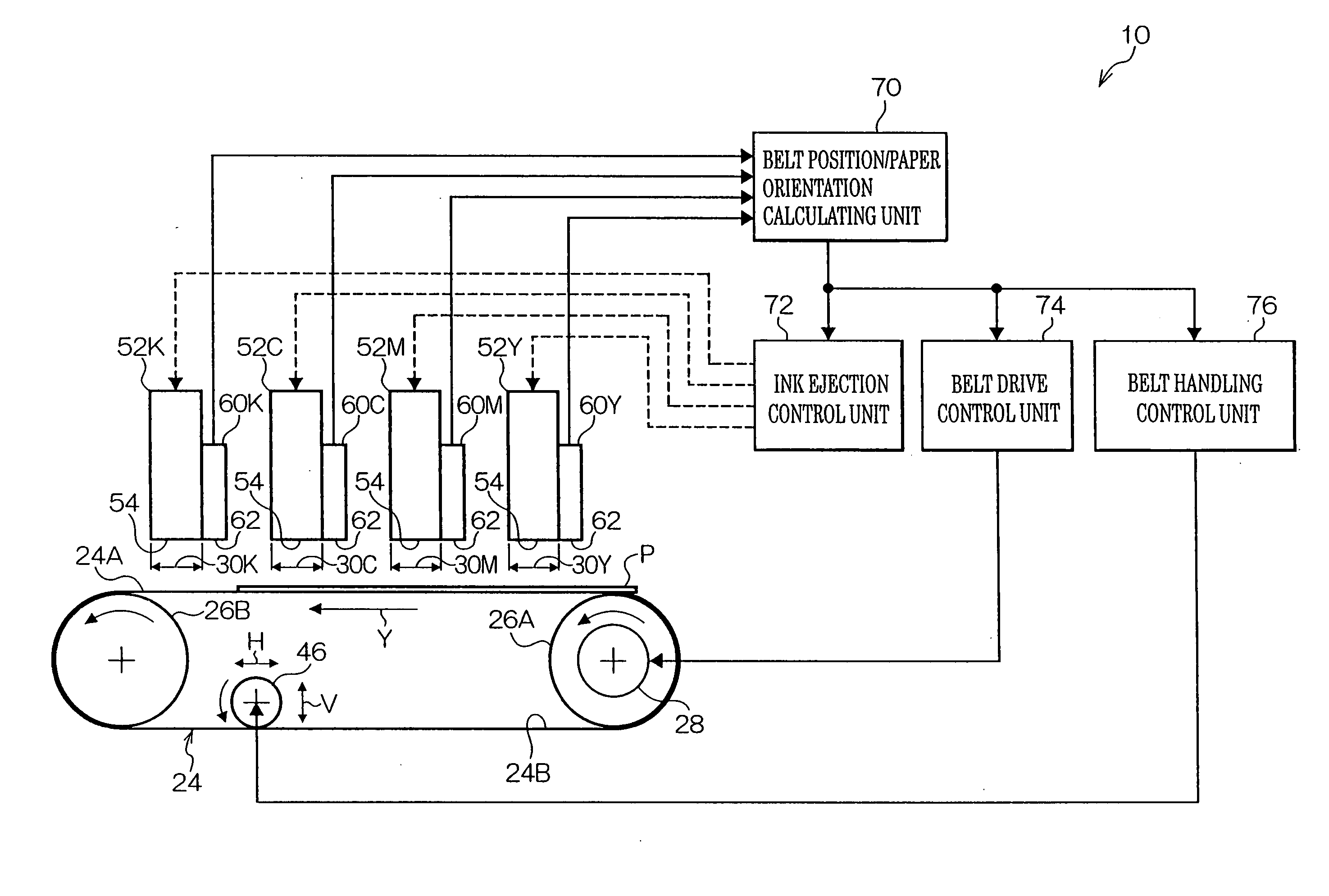
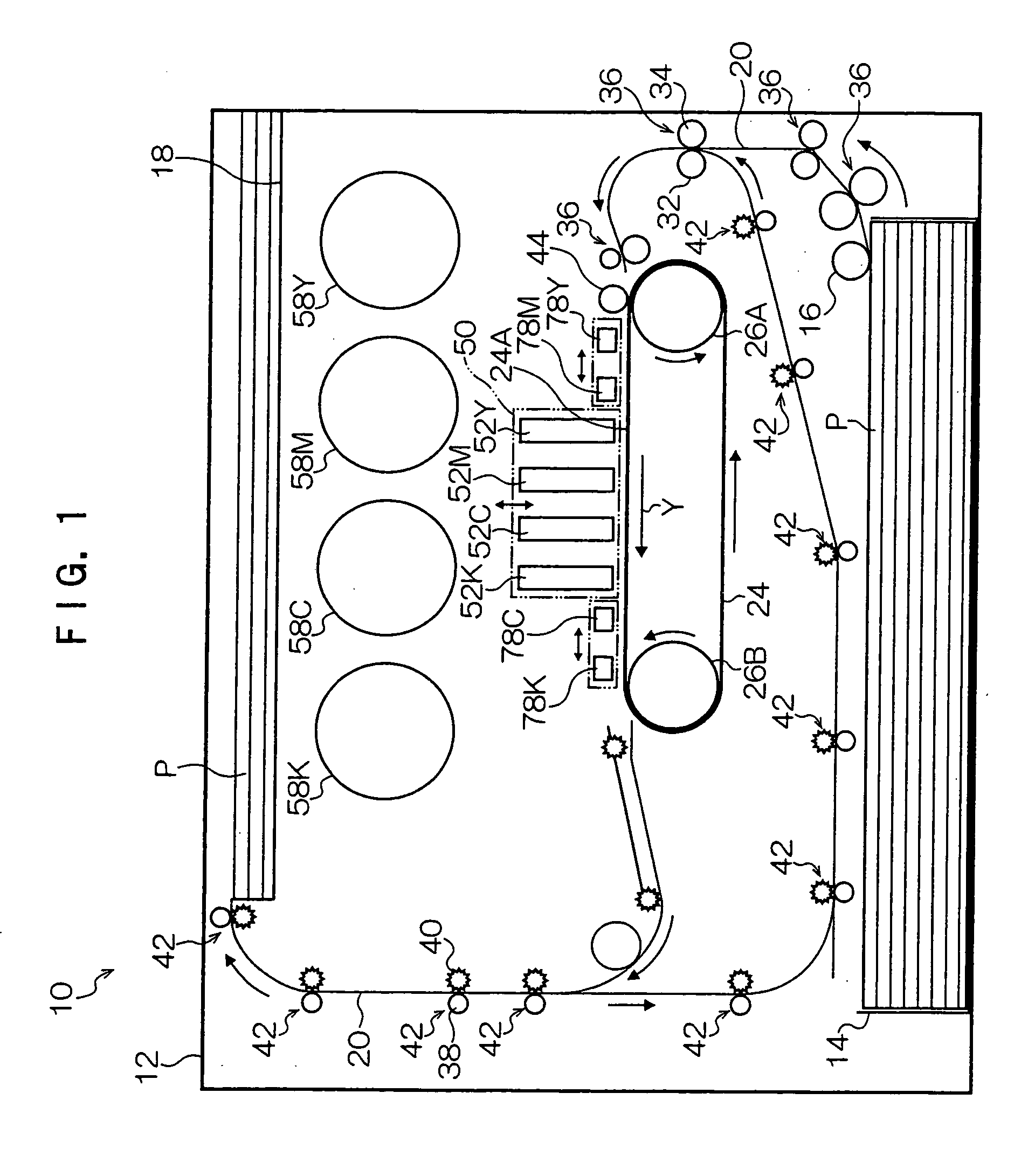
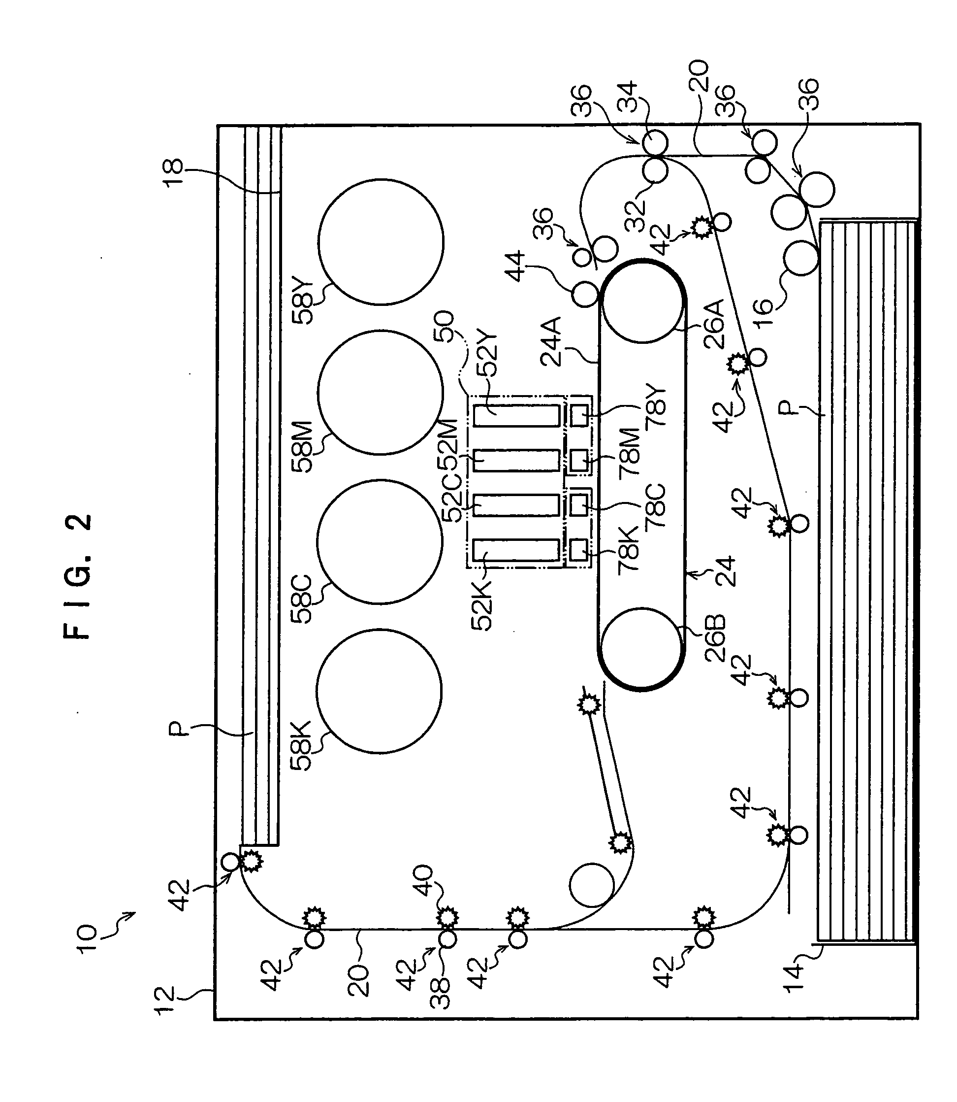
[0034] As shown in FIG. 1, an image recording apparatus (inkjet recording apparatus) 10 according to a first embodiment of the present invention includes an image recording apparatus body 12 in which a paper feed tray 14 storing stacked sheets of paper P is disposed on the bottom thereof.

[0035] Above the fore end of the paper feed tray 14 is provided a pick-up roller 16 which is disposed in pressure contact with the fore end portion of the upper surface of the top sheet of paper P upwardly biased by means of a load plate (not shown) accommodated in the paper feed tray 14. The pick-up roller is adapted to be rotated to a predetermined extent by a printing operation of the image recording apparatus 10, and to thus feed the top sheet of paper P from inside the paper feed tray 14.

[0036] Further, above the paper feed tray 14 is provided a transport path 20 which is extended, while being curved in approximately an S shape, upwardly from a position adjacent to the fore end portion of the...

second embodiment

[0098] According to a second embodiment of the present invention, the reference patterns provided on the transport belt in the image recording apparatus 10 according to the first embodiment are modified. The reference patterns of the transport belt according to the second embodiment will be described below.

[0099]FIG. 12 illustrates reference patterns 80 provided on the surface 24A of the transport belt 24 according to this embodiment.

[0100] As shown in FIG. 12, the reference patterns 80 according to this embodiment are X-shaped patterns defined by crossing of plural slant lines sloped down to the right and arranged in uniformly spaced parallel relationship with each other and plural slant lines sloped down to the left and arranged in uniformly spaced parallel relationship with each other, on the assumption that the surface 24A is viewed with the direction of rotational movement of the transport belt 24 directed upward. The reference patterns 80 are also colored to be in high contr...

third embodiment

[0103] According to a third embodiment of the present invention, the reference patterns provided on the transport belt in the image recording apparatus 10 according to the first embodiment are modified into patterns different from the ones according to the second embodiment. The reference patterns of the transport belt according to the third embodiment will be described below.

[0104]FIG. 13 illustrate reference patterns 90 which are plurally provided on the surface 24A of the transport belt 24.

[0105] As shown in FIG. 13, the reference patterns 90 according to this embodiment are slant line-like patterns sloped down to the left when the surface 24A is viewed with the direction of rotational movement of the transport belt 24 directed upward. Further, the respective reference patterns 90 are arranged in the form of a matrix such that the reference patterns 90 are arrayed with predetermined spacing in a widthwise direction (direction indicated by arrows W in FIG. 13) perpendicular to t...


PUM


Abstract

In an image recording apparatus, reference patterns are provided on a surface of a transport belt that transports a recording medium such as paper attracted thereto to image recording sections defined by recording heads. It is arranged such that the reference patterns are detected while being transported as the transport belt is driven, and a speed change of the transport belt and a position shift in a direction perpendicular to the transporting direction of the transport belt are calculated based on information resulting from the detection, thereby controlling ejection timing and ejection position of ink droplets ejected from the recording heads.

Description

[0001] Cross-Reference claims priority under 35 USC 119 from Japanese Patent Application No. 2004-261256, the disclosure of which is incorporated by reference herein. BACKGROUND OF THE INVENTION [0002] 1. Field of the Invention [0003] The present invention relates to an image recording apparatus, and more particularly it pertains to an image recording apparatus wherein an image is recorded on a recording medium supported on and transported by a transport member, by ejecting ink droplets from plural ink ejection ports provided in recording heads. [0004] 2. Description of the Related Art [0005] In an image recording apparatus of the inkjet type in which an image is recorded on paper (recording medium) by ejecting ink droplets from recording heads, a printing system called a serial scan system is widely used primarily for personal use, wherein the paper is transported and printing is performed on a line-by-line basis by reciprocally moving recording heads in a direction perpendicular t...

Claims


Application Information

Patent Timeline
IPC IPC(8): B41J29/393
CPCB41J11/007B41J11/008B41J11/42
Inventor MURAKAMI, ATSUSHIMIHARA, AKIRASATOH, HIROAKIFURUYA, MASAMIITAZU, KISHIHARUIKEDA, HIROSHI
Owner FUJIFILM BUSINESS INNOVATION CORP
Why Eureka
Try Eureka