
Rotation system with three degrees of freedom and application of the same

a technology of rotating system and freedom, applied in the field of rotating system with three degrees of freedom, can solve the problem of hollow rotor of said system

Inactive Publication Date: 2006-03-09
ECCHANDES
View PDF1 Cites 9 Cited by
  • Summary
  • Abstract
  • Description
  • Claims
  • Application Information

AI Technical Summary

Benefits of technology

[0009] The invention described in claim 3 is a rotation system with three degrees of freedom according to claim 1 or 2, wherein a fourth guide rail is installed on said indication bar, and said slider slides along said fourth guide rail. Said fourth guide rail may be in a shape of a bar, or may have a slit. In particular, in a case that this said guide rail has this said slit, this said guide rail may be cut out from a plate, or may be constructed by combining with at least two wires. Suppose moreover that this said guide rail is in a shape of an umbrella. In this case, this said guide rail can increase the strength. This said guide rail rotates centering around said indication bar. Therefore, since at least one said slider slides along this said guide rail, a rotation direction of this said indication bar coincides with a direction of this said slider viewed from this said indication bar. By detecting a direction of this said indication bar and a direction of these guide rails, thus, a rotation direction of this said indication bar is derived precisely. Since said rotor can be rotated with three degrees of freedom without moving all said bases, in the present invention, many problems on a rotation system with three degrees of freedom are solved very well.
[0012] The invention described in claim 5 is a rotation system with three degrees of freedom according to claim 4, wherein said indication bar passes through a slit, which is opened in said first guide rail. Said first guide rail may be cut out from a plate, or may be constructed by combining at least two wires. Said first guide rail rotates centering around two said shafts. Therefore, since said indication bar passes through said slit opened in this guide rail, a direction of this said indication bar coincides with a direction of this said guide rail. By detecting a direction of this guide rail, thus, a rotation angle of this said indication bar centering around two said shafts supporting this said guide rail is derived precisely. Since a direction of said indication bar can be decided without spending time and effort too much, in the present invention, many problems on a rotation system with three degrees of freedom are solved very well.
[0022] The invention described in claim 14 is a rotation system with three degrees of freedom according to any one of claims 1 to 13, wherein at least one encoder detects a direction of said rotor, by detecting at least one rotation angle of said guide rails, said shafts and said bearings. By detecting at least one said rotation angle of said guide rails, said shafts and said bearings, said encoder can detect said rotation angle of a corresponding said guide rail. Here, said encoder may be fixed directly to at least one said base, or may be connected to these said bases via spacers and a case. Even in a case of using three said encoders, since a direction of said rotor can be detected without moving these said encoders, in the present invention, many problems on a rotation system with three degrees of freedom are solved very well.
[0027] The invention described in claim 19 is a rotation system with three degrees of freedom according to claim 14, 15 or 16, wherein a computer system calculates a rotation angle of said rotor, by connecting at least one said encoder to said computer system. Said computer system inputs an electric signal corresponding to at least one rotation angle of said guide rails, said shafts and said bearings, where said electric signal is outputted from at least one said encoder. Therefore, even though said electric signal of said encoder is not in proportion to said rotation angle of said rotor, said computer system can calculate this said rotation angle from this said electric signal, by using equations and tables. Since a gap between said electric signal of said encoder, which is generated according to a position of said indication bar, and said rotation angle of said rotor can be corrected, in the present invention, many problems on a rotation system with three degrees of freedom are solved very well.

Problems solved by technology

Moreover, this said rotor may be hollow.

Method used


Image

  • Rotation system with three degrees of freedom and application of the same
  • Rotation system with three degrees of freedom and application of the same
  • Rotation system with three degrees of freedom and application of the same

Examples


Embodiment Construction

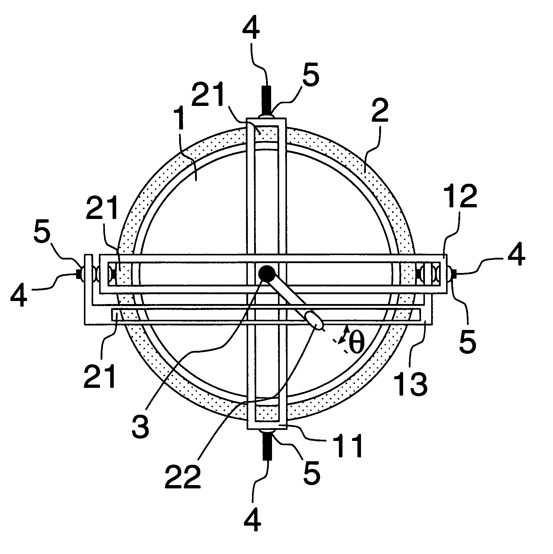
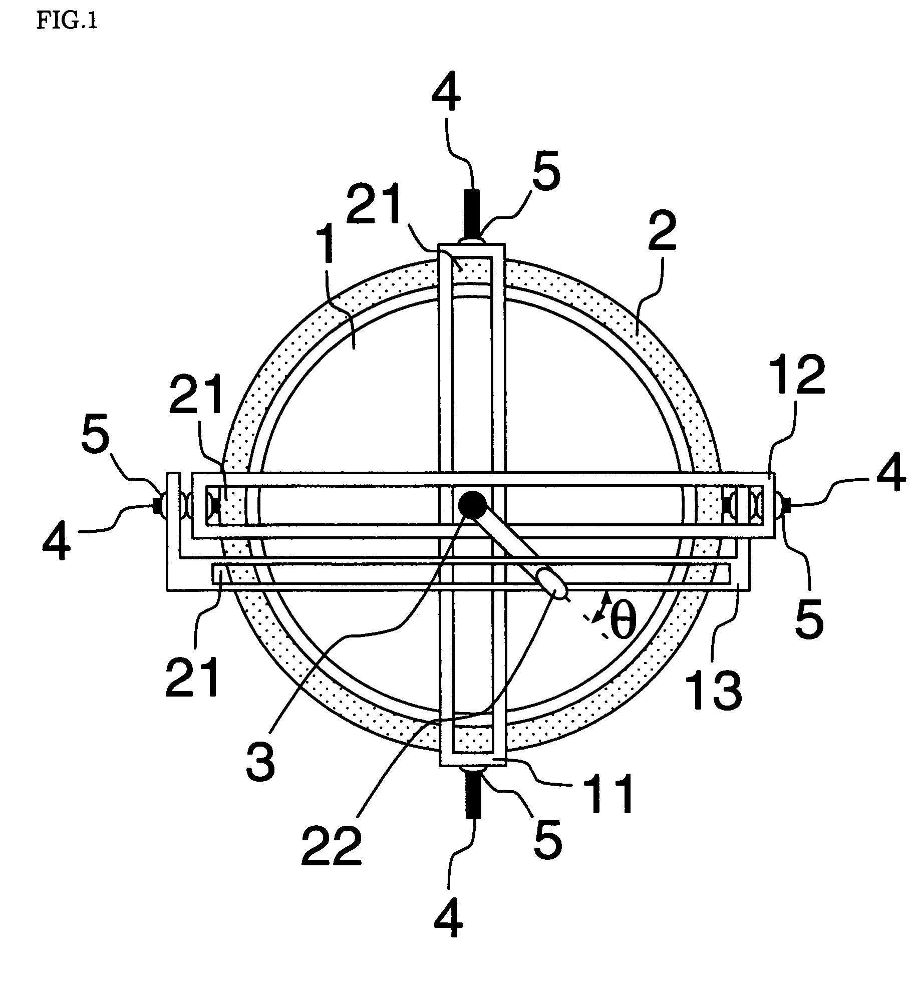
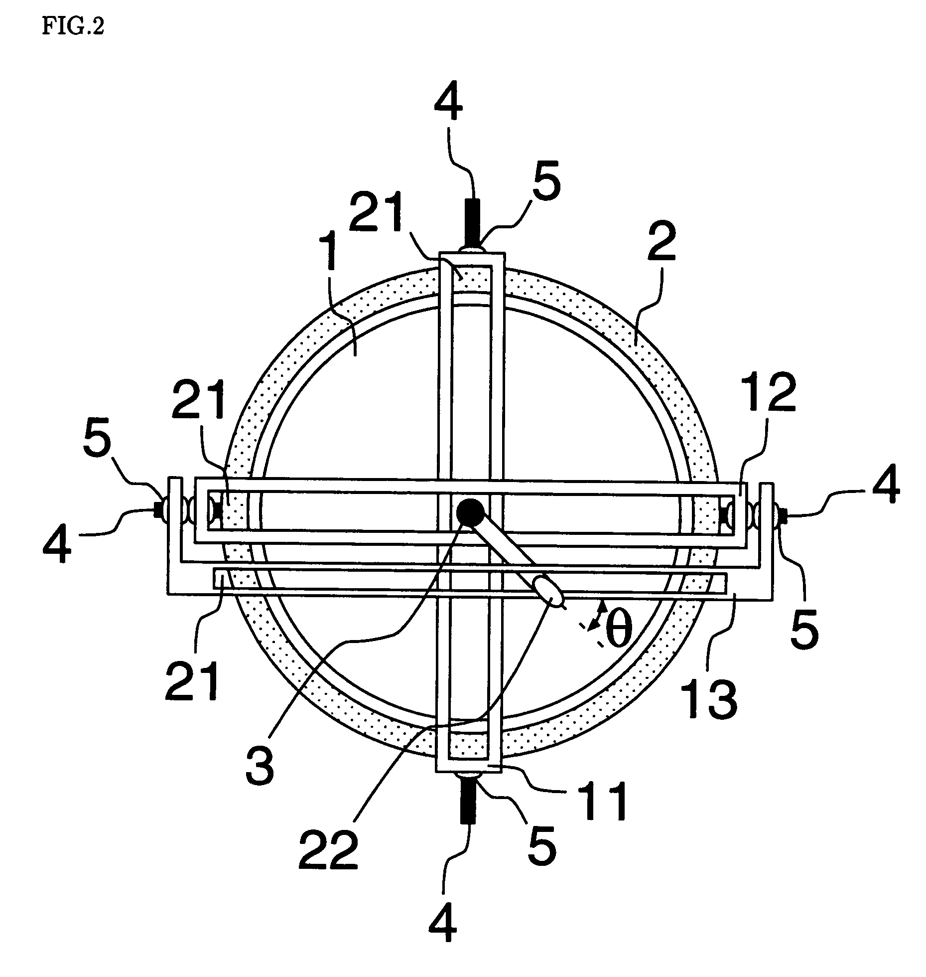
[0071] Some enforcement forms of a rotation system with three degrees of freedom using a first guide rail 11, a second guide rail 12 and a third guide rail 13 in the present invention are shown below. With reference to the drawings, then, it is explained about the enforcement forms.

[0072] As shown in FIG. 1 and FIG. 2, basic structure of a rotation system with three degrees of freedom is spherical surface bearing structure which is combined a spherical rotor 1 and a base 2 hollowed out circularly. An indication bar 3 is installed on the rotor 1. Moreover, two shafts 4, on which a first guide rail 11 is installed, and two shafts 4, on which a second guide rail 12 and a third guide rail 13 are installed, are installed on the base 2 so as to be orthogonal each other. Suppose here that the indication bar 3 is arranged at a place where the first guide rail 11, and the second guide rail 12 and the third guide rail 13 cross. In this case, the indication bar 3 can move along these guide ra...


PUM


Abstract

As shown in FIG. 1, a first guide rail (11), and a second guide rail (12) and a thrid guide rail (13) that are parallel to each other are installed on a base (2) so as to be perpendicular to each other, and these guide rails are rotated about shafts (4) installed on both ends. When the guide rails are rotated, an indication bar (3) installed on a rotor (1) is moved synchronously with the movement of the guide rails, so that the rotor (1) is also rotated. A slider (22) installed on the indication bar (3) slides along a slit (21) of the third guide rail (13). Then a rotation angle of the rotor (1) about the indication bar (3) is determined by the distance between the guide rails.

Description

FIELD OF THE INVENTION [0001] The present invention relates to a rotation system with three degrees of freedom, using at least three guide rails, wherein one of the guide rails and two other guide rails are installed on a base so as to be orthogonal to each other, an indication bar is installed on a rotor, and at least one slider is installed on the indication bar, which detect a direction of the rotor by rotating the guide rails, sliding along the guide rails, and rotate the rotor by rotating the guide rails by actuators. BACKGROUND OF THE INVENTION [0002] Many motors with three degrees of freedom like ones using a piezoelectric element (refer to Published Unexamined Japanese Patent Application No. S62-228392, Published Unexamined Japanese Patent Application No. H09-34409, Published Unexamined Japanese Patent Application No. H09-219980, Published Unexamined Japanese Patent Application No. H11-18459 and PCT Publication Number WO 02 / 15358), ones using a synchronous motor (refer to To...

Claims


Application Information

Patent Timeline
Patent Type & Authority Applications(United States)
IPC IPC(8): H04N5/225B25J17/02F16H21/48F16H21/54F16M11/12F16M11/18
CPCB25J17/0283F16H21/48F16H21/54F16M11/18F16M11/048F16M11/12F16M11/14F16M11/045
Inventor AJIOKA, YOSHIAKI
Owner ECCHANDES
Learn More