Optical projection apparatus and assembling method thereof

a technology of optical projection and assembling method, which is applied in the direction of printers, instruments, cameras, etc., can solve the problems of inability to perform simple image focusing operation and directional adjustment, and inability to control, etc., to achieve shortening production time, improving focusing characteristic, and reducing production cost

Inactive Publication Date: 2006-03-09
DELTA ELECTRONICS INC
View PDF1 Cites 7 Cited by
  • Summary
  • Abstract
  • Description
  • Claims
  • Application Information

AI Technical Summary

Benefits of technology

[0010] Accordingly, the primary object of the present invention is to provide an optical projection apparatus and assembling method thereof for

Problems solved by technology

Because a number of components are disposed between the display module 120 and the projection lens 110, cumulative tolerance is often produced leading to some instability in the quality of the focused image.
Furthermore, the lens calibration assembly 150 can only perform simple image focusing operation and directional adjustments.
Such adjustment is not only time-consuming, but also

Method used


Image

  • Optical projection apparatus and assembling method thereof
  • Optical projection apparatus and assembling method thereof
  • Optical projection apparatus and assembling method thereof

Examples


Embodiment Construction

[0036] Reference will now be made in detail to the present preferred embodiments of the invention, examples of which are illustrated in the accompanying drawings. Wherever possible, the same reference numbers are used in the drawings and the description to refer to the same or like parts.

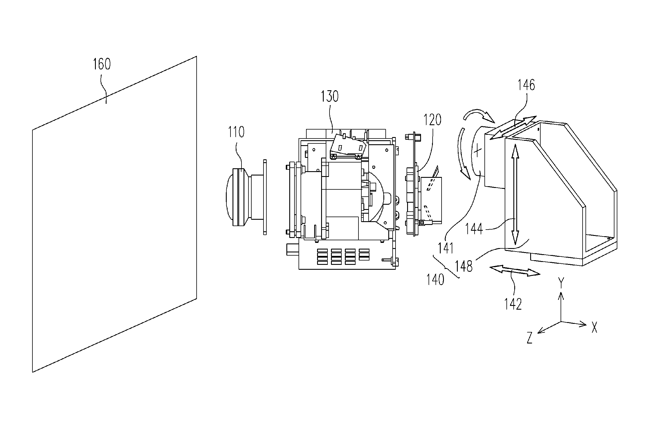
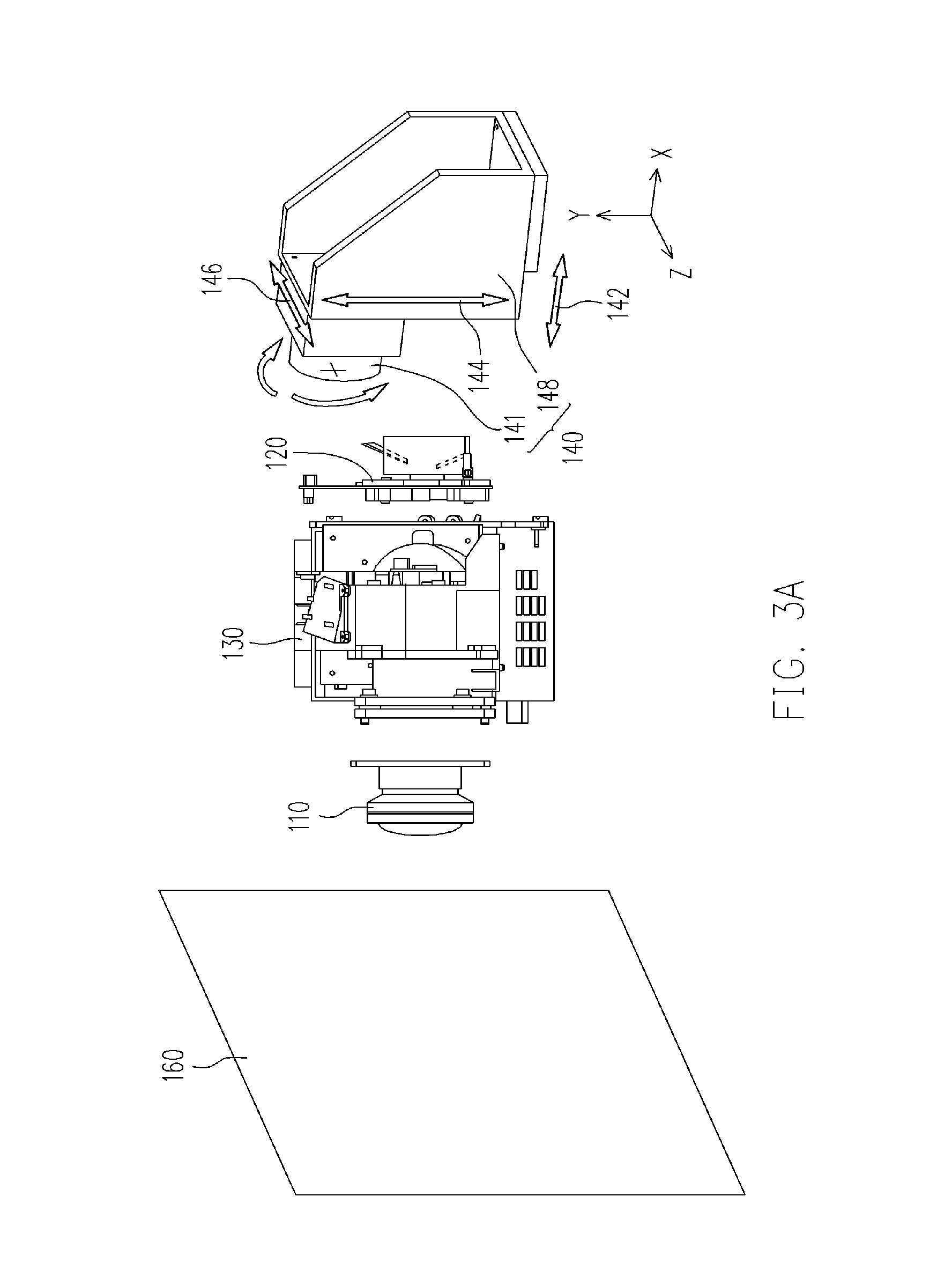
[0037] As shown in FIGS. 2, 3A and 4, a projection lens 110, a display module 120 and an optical engine 130 are provided. The display module 120 further comprises a frame 121, a display device fastener module comprising a first holder 122 and a second holder 125, a display device 123, and a circuit board 124. The display device 123 is a digital micro-mirror device, for example. In addition, the frame 121 comprises a plurality of device positioning holes 121 a and a plurality of gluing holes 121b, for example.

[0038] In one preferred embodiment of the present invention, a set of locking elements 128b is used to tighten the first holder 122, the circuit board 124 and the second holder 125 to the devi...


PUM


Abstract

An optical projection apparatus and assembling method thereof are disclosed. The method includes providing a precise calibration fixture, a projection lens, a display module and an optical engine. The projection lens and the optical engine and then the display module and the precise calibration fixture are assembled together. An image calibration operation is performed so that the position of the display module relative to the projection lens is adjusted through the precise calibration fixture. Thereafter, the display module and the optical engine are assembled using glue. The aforementioned apparatus and assembling method can improve the focusing characteristic of images and resolve image-tilting and image-shifting problems.

Description

CROSS-REFERENCE TO RELATED APPLICATION [0001] This application claims the priority benefit of Taiwan application serial no. 93126971, filed on Sep. 7, 2004. All disclosure of the Taiwan application is incorporated herein by reference. BACKGROUND OF THE INVENTION [0002] 1. Field of the Invention [0003] The present invention relates to an optical projection apparatus and assembling method thereof. More particularly, the present invention relates to an optical projection apparatus and assembling method thereof that can improve focusing characteristic, resolve image-tilting and image-shifting problems, shorten production time and reduce cost. [0004] 2. Description of the Related Art [0005] In recent years, liquid crystal display devices are increasingly used in direct viewing display devices, such as display screens, notebook computers, digital television. Moreover, liquid crystal display devices are also used in indirect viewing display devices deployed by liquid crystal projectors and...

Claims


Application Information

Patent Timeline
IPC IPC(8): G03B21/14
CPCG03B21/14G03B3/00G03B5/00G03B21/10G03B21/142
Inventor HSU, TSUNG-JUNGCHEN, CHING-CHAO
Owner DELTA ELECTRONICS INC
Why Eureka
Try Eureka