
Method of correcting deflection defocusing in CRT, CRT employing same, and image display system including same CRT

A technology for cathode ray tubes and cathodes, applied in the direction of cathode ray tubes/electron beam tubes, discharge tubes, electrode devices and related components, which can solve the problems of increasing circuit costs and manufacturing processes

Inactive Publication Date: 2003-07-02
HITACHI LTD
View PDF8 Cites 0 Cited by
  • Summary
  • Abstract
  • Description
  • Claims
  • Application Information

AI Technical Summary

Problems solved by technology

This requires a dynamic focus voltage generator for the corresponding deflection frequency and adjusts the focus voltage at the corresponding frequency to deflect the electron beam, thus increasing the circuit cost and manufacturing process, and varies with the size of the cathode ray tube screen and the maximum deflection angle increases exponentially

Method used


Image

  • Method of correcting deflection defocusing in CRT, CRT employing same, and image display system including same CRT
  • Method of correcting deflection defocusing in CRT, CRT employing same, and image display system including same CRT
  • Method of correcting deflection defocusing in CRT, CRT employing same, and image display system including same CRT

Examples


Embodiment Construction

[0139] The method for correcting deflection defocus, the cathode ray tube using the method and the image display system including the cathode ray tube of the present invention have the following advantages:

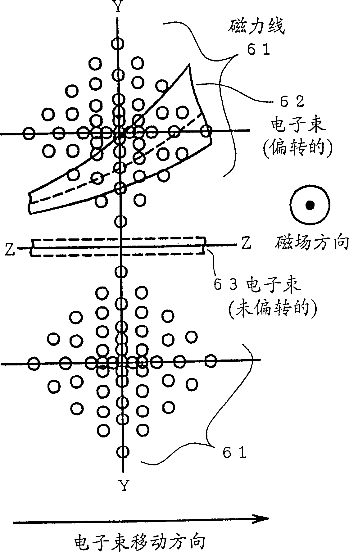
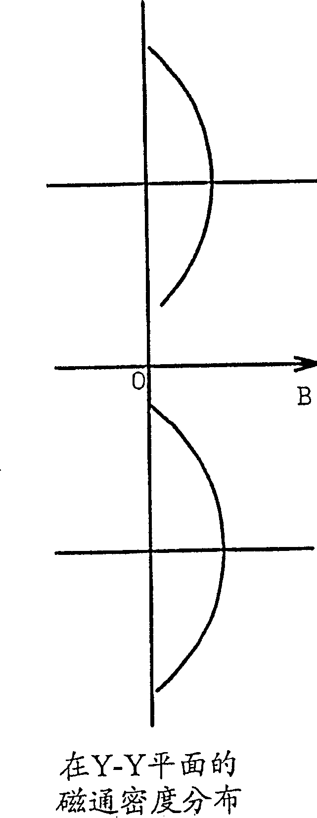
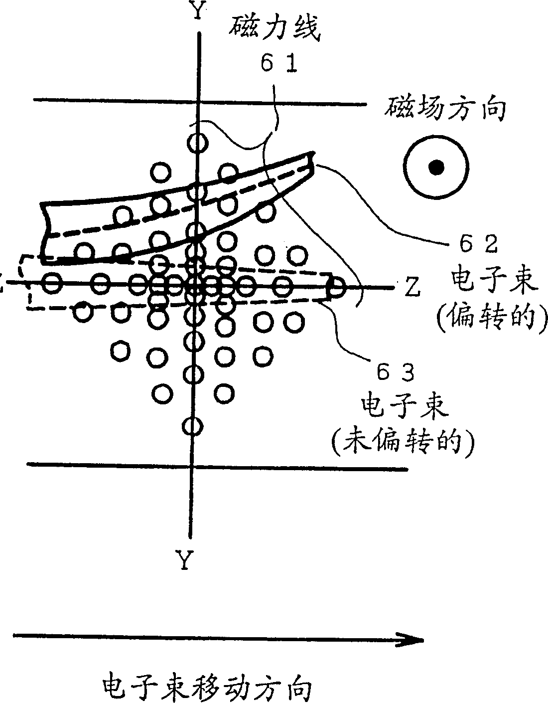
[0140] (1) Generally, as the deflection amount increases in a cathode ray tube, the deflection defocus amount rapidly increases. According to the present invention, deflection defocusing can be corrected by providing a magnetic member in the deflection magnetic field for forming a locally modified non-uniform magnetic field which is locally modified when the electron beam is deflected and changes trajectory by the deflection magnetic field. It has a variable convergence and divergence effect on the electron beam.

[0141] (2) Figure 64 is a curve representing the relationship between the amount of deflection (deflection angle) and the amount of deflection defocus; Figure 65 is a graph showing the relationship between the deflection amount and the deflection defocus co...


PUM


Abstract

A method corrects deflection defocusing in a cathode ray tube including an electron gun comprising a plurality of electrodes, an electron beam deflection device and a phosphor screen. This method includes placement of pole pieces of magnetic material in a deflection magnetic field produced by the electron beam deflection device and thereby locally modifies the deflection magnetic field in a path of an electron beam and corrects deflection defocusing of the electron beam corresponding to deflection of the electron beam in amount.

Description

technical field [0001] The present invention relates to cathode ray tubes, and in particular to a method for correcting deflection defocus in cathode ray tubes, which method enables improved focusing characteristics and thus sufficient resolution over the entire phosphor screen and in all electron beam current ranges; in particular A cathode ray tube using the method and an image display system including the cathode ray tube. Background technique [0002] A cathode ray tube, such as a picture tube or a display tube, at least includes an electron gun with a plurality of electrodes and a fluorescent screen (the screen has a fluorescent film, and the screen is also referred to as "fluorescent film" hereinafter referred to as "screen". A deflection device for scanning on a fluorescent screen. [0003] For such a cathode ray tube, the following techniques are known to obtain a desired reproduced image over the entire phosphor screen from the center to the peripheral portion. ...

Claims


Application Information

Patent Timeline
Patent Type & Authority Patents(China)
IPC IPC(8): H01J29/56H01J29/70
CPCH01J29/707
Inventor 御园正义
Owner HITACHI LTD
Learn More