Method for astigmatism regulation for optical wave-pick-up device

A technology of astigmatism adjustment and pick-up, which is applied in the field of astigmatism adjustment of optical pick-up units, can solve the problems of evaluation machine not having functions and time constraints, and achieve the effect of high reliability and stable servo system

Inactive Publication Date: 2006-04-19
PIONEER CORP
View PDF0 Cites 0 Cited by
  • Summary
  • Abstract
  • Description
  • Claims
  • Application Information

AI Technical Summary

Problems solved by technology

[0009] That is, in order to adjust, it is necessary to repeatedly perform adjustment and measurement, but there is a time limit for such adjustment and measurement during the production process, and the evaluation machine does not have such a function

Method used


Image

  • Method for astigmatism regulation for optical wave-pick-up device
  • Method for astigmatism regulation for optical wave-pick-up device
  • Method for astigmatism regulation for optical wave-pick-up device

Examples


Embodiment Construction

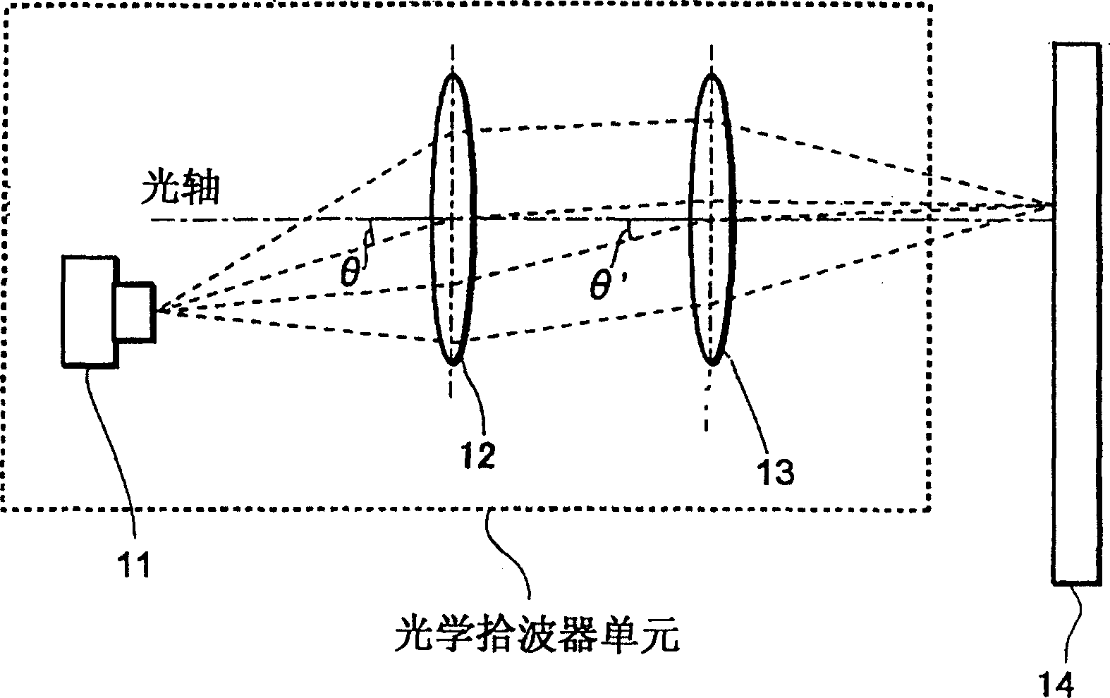
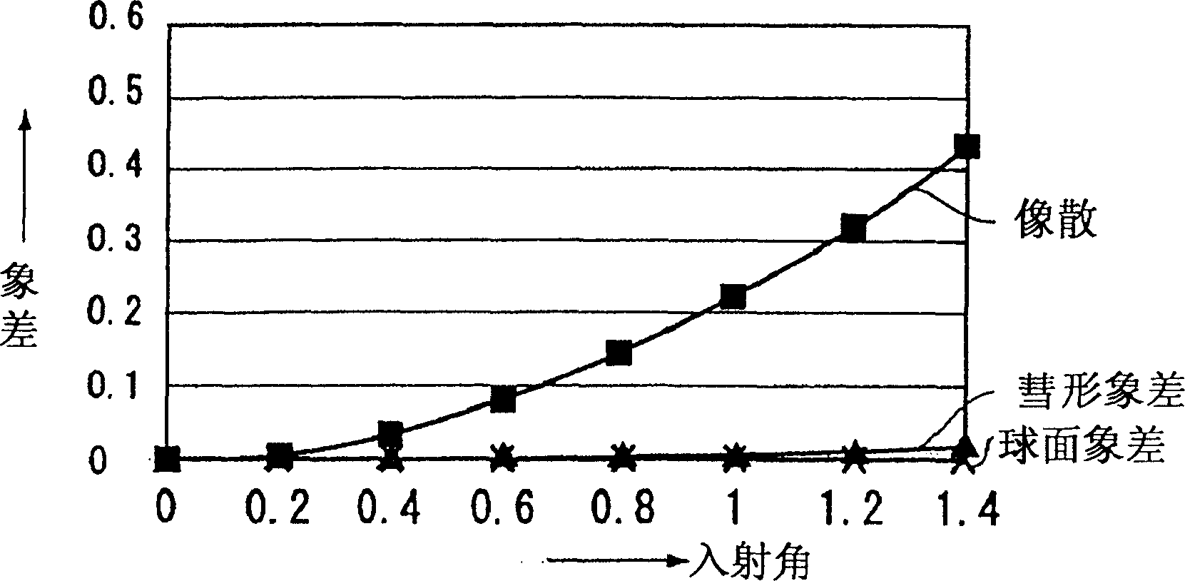
[0037] As we all know, in figure 1 In the optical pickup unit shown by the collimator lens 12, laser diode (hereinafter referred to as LD) 11, the objective lens 13 that focuses the light beam on the recording medium 14, the light beam generated and output by the LD11 is incident on the The angles θ, θ′ of the collimator lens 12 and the objective lens 13 determine the amount of astigmatism. figure 2 It is a graph of the amount of aberration when the LD 11 is moved in any direction on a plane perpendicular to the traveling direction of the light beam and the incident angle of the light beam to the lens is changed.

[0038] In the present invention, by moving LD 11 in any direction on a plane perpendicular to the traveling direction of the light beam, the incident angle of the light beam to the collimator lens 12 and the objective lens 13 is changed, and the light beam is adjusted to a state where astigmatism does not occur as much as possible.

[0039] Although the light beam...


PUM


Abstract

The invention manufacture an optical pickup unit which is high in the condensing characteristics necessary for recording and reproducing of a recording medium subjected to high-density recording. The method and device for regulating the astigmatism of an optical pickup unit consisting of at least a laser diode and an optical system for condensing the light beam formed by the laser diode to a recording medium as components consist in capturing the sectional shape of the light beam as an image by an image processor, measuring out-of-roundness from the relation between the major axis and minor axis of the captured image and moving the laser diode on the plane perpendicular to the progressing direction of the light beam with the nearly truly round position as an optimum position, thereby changing the incident angle of the light beam to the optical system and regulating the astigmatism.

Description

technical field [0001] The present invention relates to an image pick-up unit with at least a laser diode, a collimator lens for converting the light beam from the laser diode into parallel light, and an objective lens for focusing the light beam from the collimator lens on a recording medium. Dispersion adjustment method and device. Background technique [0002] The optical pickup unit performs optical signal detection, and it can be said to be the heart of optical products such as CD (Compact Disc) players. [0003] Such as figure 1 As shown, the constituent parts of the optical pickup unit can be roughly divided into three parts: a laser diode 11 , a collimator lens 12 , and an objective lens 13 . Here, a collimating lens 12 is added between the laser diode 11 and the objective lens 13 , and the parallel light is incident on the objective lens 13 and then focused on the optical disc recording medium 14 . [0004] However, in the above-mentioned CD player, by appropriat...

Claims


Application Information

Patent Timeline
Patent Type & Authority Patents(China)
IPC IPC(8): G11B7/08G11B19/12G02B7/00G11B7/135G11B7/22
CPCG11B7/08G11B7/127G11B7/1374G11B7/1376G11B2007/13727G11B2220/2566
Inventor 桑原庆成千田勇人大内秀和村上哲也滝口仁史熊丸靖岩田达也川村诚松本高明菅野光俊势田吉宏茂木武都
Owner PIONEER CORP
Why Eureka
Try Eureka