Image display device, portable terminal, display panel, and lens

a display device and portable terminal technology, applied in optics, instruments, electrical devices, etc., can solve the problems of obstructing the view, burden of wearing, and no-eyeglass system using no eyeglasses, and achieve the effect of preventing deterioration in display quality

Active Publication Date: 2006-03-09
NEC LCD TECH CORP
View PDF3 Cites 52 Cited by
  • Summary
  • Abstract
  • Description
  • Claims
  • Application Information

AI Technical Summary

Benefits of technology

[0048] It is an object of the present invention to provide an image display device capable of preventing deterioration in display quality caused by shading portions of a display panel, a portable terminal device equipped with the same, and a display panel incorporated in the image display device.

Problems solved by technology

Of these, the systems using eyeglasses include an anaglyph system, a polarizing eyeglass system utilizing polarization and the like, however, with these systems, since the burden of wearing eyeglasses cannot be essentially avoided, no-eyeglass systems using no eyeglasses have been investigated in recent years.
In the aforementioned parallax barrier system, since the parallax barrier had been initially arranged between the pixels and eyes when this was devised, this had obstructed the view and there had been a problem of low visibility.
However, the aforementioned prior arts have the following problems.
When a viewer had shifted his / her view position from images for respective viewpoints, he / she is to view non-display areas, however, since no display is carried out in the non-display areas as mentioned above, the viewer cannot view an image.
Moreover, generally, it is improbable that a viewer views only at an optimal view position, and a shift in the view position can frequently occur.
As a result, the viewer is conscious of a situation where viewing an image is impossible.
Since no such situation occurs in an ordinal image display device having no optical components for image sorting, the viewer senses that, in an image display device which can display different images at a plurality of viewpoints, display quality is considerably deteriorated in comparison with the ordinal image display device.
Accordingly, when a viewer is positioned at the non-display area, since the viewer cannot recognize an image, he / she senses that the display quality has been considerably deteriorated.
Similar problems occur in three-dimensional image display devices not only by lens systems but also by parallax barrier systems.
When. a viewer is positioned at the non-display area, the viewer cannot recognize an image; he / she senses that display quality has been considerably deteriorated.
Furthermore, a similar problem occurs in a three-dimensional image display device provided with a parallax barrier in the rear of a display panel, as well.
When a viewer is positioned at the non-display area, the viewer cannot recognize an image; he / she senses that display quality has been considerably deteriorated.
Although a description has been given of a deterioration in display quality caused by a shading portion of a display panel while raising the examples of conventional three-dimensional image display devices, this problem is not limited to the three-dimensional image display devices and can similarly occur in image display devices as long as these are provided with optical components such as lenticular lenses and parallax barriers and the like.

Method used


Image

  • Image display device, portable terminal, display panel, and lens
  • Image display device, portable terminal, display panel, and lens
  • Image display device, portable terminal, display panel, and lens

Examples


first embodiment

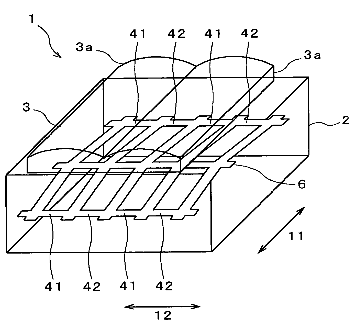
[0133] Hereinafter, image display devices according to embodiments of the present invention will be described in detail with reference to the accompanying drawings. First, description is given of an image display device according to the present invention. FIG. 9 is a perspective view showing a part of an image display device of the present embodiment, and FIG. 10 is a plan view showing a display panel thereof. As shown in FIG. 9, in an image display device 1 of the present embodiment, a lenticular lens 3, a display panel 2, and a light source (unillustrated) are provided in order from a viewer side. The display panel 2 is, for example, a transmission liquid crystal panel. This display panel 2 is composed of a large number of display pixels, and each display pixel is composed of a pair of adjacent first viewpoint pixel 41 and second viewpoint pixel 42. Here, in FIG. 9, for the sake of improvement in visibility of the drawing, borders between cylindrical lenses 3a on the display panel...

second embodiment

[0148] Next, description is given of an image display device according to the present invention. FIG. 18 is a plan view showing a display panel of an image display device of the present embodiment. As shown in FIG. 18, in an image display device 13 of the present embodiment, of respective openings 15 of first viewpoint pixels 41 and second viewpoint pixel 42, sides which intersect with straight lines extending in a horizontal direction 12 are composed of straight lines parallel to a vertical direction 11 and straight lines vertical to the same, and the openings 15 have shapes with a dislocation in the horizontal direction 12 in the vicinities of center portions. Accordingly, position of the openings in this display panel14 varies depending on the position in the vertical direction 11.

[0149]FIG. 19 is an optical model diagram of a section along a line D-D shown in FIG. 18. As shown in FIG. 19, in the section along the line D-D, position of the openings 15 of the first viewpoint pixel...

third embodiment

[0155]FIG. 24 is a graph showing distribution of brightness on a view plane of the image display device of the present invention while taking a viewing position on the horizontal axis and brightness on the vertical axis. In the image display device of the present embodiment, since the sides of the openings 25 of the display panel which intersect with straight lines extending in the horizontal direction 12 are composed of curved lines, distribution of brightness on a view plane can be made into an arbitrary shape, and for example, into a shape of distribution as shown in FIG. 24, setting with a higher degree of freedom according to desirable optical characteristics becomes possible.

[0156] In addition, in the image display device of the present embodiment, the number of corners of each opening 25 surrounded by a shading portion 26 can be minimized to four, and furthermore, all corners can be made into right angles. Namely, no such acute-angled corners are formed as in the image displa...


PUM


Abstract

In an image display device where a lenticular lens, a display panel, and a light source are provided in order from a viewer side, when cylindrical lenses of the lenticular lens are arrayed in a horizontal direction, in first-viewpoint pixels and second-viewpoint pixels of the display panel, openings whose sides which intersect with straight lines in the horizontal direction are not parallel to a vertical direction are formed. And, a shape of the openings of a pair of pixels mutually adjacent in the vertical direction is made line-symmetric with respect to edges of the pixels extending in the horizontal direction as an axis.

Description

BACKGROUND OF THE INVENTION [0001] 1. Field of the Invention [0002] The present invention relates to an image display device capable of displaying different images at a plurality of viewpoints, a portable terminal equipped with the same, and a display panel and a lens incorporated in the image display device, and in particular, it relates to an image display device capable of displaying a three-dimensional image with an excellent quality, a portable terminal, a display panel, and a lens. [0003] 2. Description of the Related Art [0004] Priorly, image display devices capable of displaying different images at a plurality of viewpoints have been investigated. As an example thereof, a three-dimensional image display device on the premise of displaying parallax images as multi-viewpoint images exists. In B.C. 280, the Greek mathematician-Euclid considered that “Three-dimensional imaging is a sensation obtained when both right and left eyes simultaneously look at different images of an ide...

Claims


Application Information

Patent Timeline
Patent Type & Authority Applications(United States)
IPC IPC(8): G02B27/26G02B30/25G02B30/27G02B30/30
CPCG02B27/2214G02B3/005H04N13/0404H04N13/305G02B30/27G02B30/30
Inventor UEHARA, SHIN-ICHIIRIGUCHI, MASAOIKEDA, NAOYASUTAKANASHI, NOBUAKI
Owner NEC LCD TECH CORP
Why Eureka
Try Eureka