
Method for automatic loudspeaker polarity determination through loudspeaker-room acoustic responses

a loudspeaker and acoustic response technology, applied in the field of loudspeaker systems, can solve the problems of erroneous polarity determination, difficulty in determining whether or not coincidence of the connection polarities of left and right loudspeakers is achieved, and polarities to be incorrectly determined

Inactive Publication Date: 2006-03-09
AUDYSSEY LABORATORIES
View PDF4 Cites 27 Cited by
  • Summary
  • Abstract
  • Description
  • Claims
  • Application Information

AI Technical Summary

Benefits of technology

"The patent describes a method for determining the polarity of a loudspeaker without using subjective tests or complex analog processing circuitry. The method involves measuring the acoustics of the loudspeaker and room using a microphone and analyzing the resulting signal. By filtering the acoustical response and measuring the sign of the first peak, the method can accurately determine the polarity of the loudspeaker. This can be useful in designing audio systems and ensuring proper sound quality."

Problems solved by technology

In the above determining method, it is difficult to determine whether or not coincidence of the connection polarities of left and right loudspeakers is attained because of the following reasons.
(b) Problem due to standing wave: In the case where a test signal having only one frequency component is used, when the frequency is close to that of the standing wave of the room, interference between the test signal and the standing wave may cause polarities to be incorrectly determined.
(d) Many home-theater receivers and amplifiers are sold to consumers that have little to no knowledge of performing listening tests, and this may lead to erroneous polarity determination.
The Fink apparatus, being confined to the testing of electrical circuits, typically inter-studio wired lines, may have functioned adequately for that purpose, however it did not anticipate acoustic testing through a microphone and thus failed to address certain inherent problems associated therewith.

Method used


Image

  • Method for automatic loudspeaker polarity determination through loudspeaker-room acoustic responses
  • Method for automatic loudspeaker polarity determination through loudspeaker-room acoustic responses
  • Method for automatic loudspeaker polarity determination through loudspeaker-room acoustic responses

Examples


Embodiment Construction

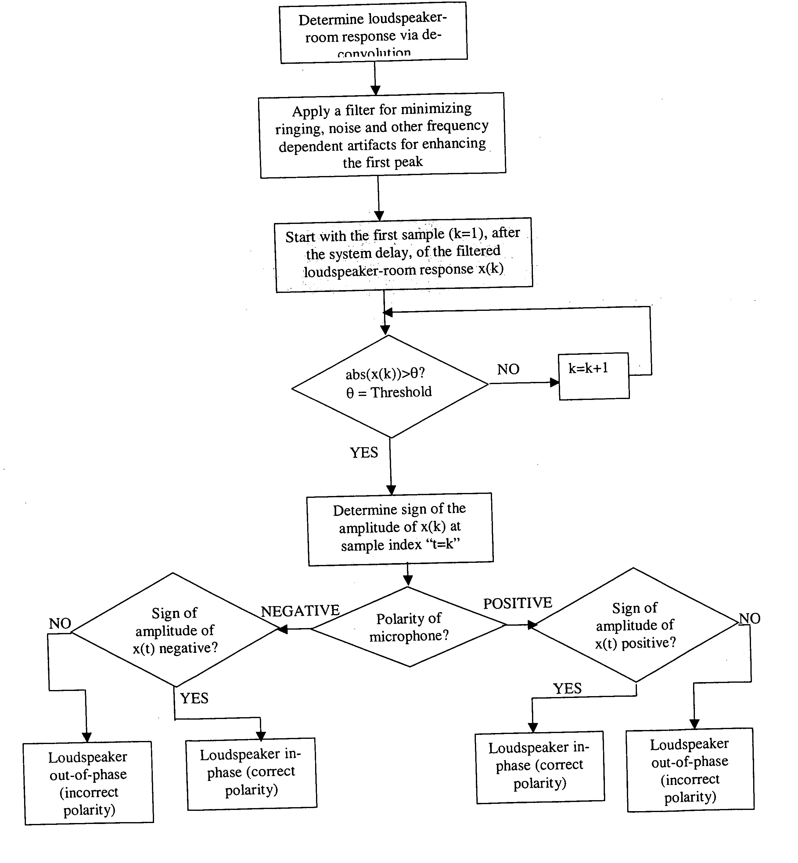
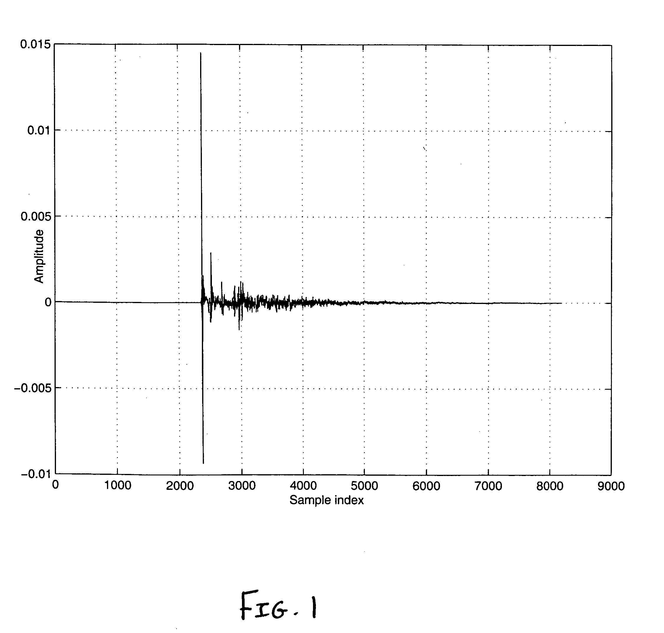
[0032] Shown in FIG. 2 is the direct path peak, as depicted by the first negative going peak, measured by a microphone with a negative polarity. Accordingly, any arbitrary signal that is convolved with this loudspeaker-room response will be measured, by the present microphone, with a negative sign of the first peak. Thus, this constitutes that the actual loudspeaker polarity is in phase (i.e., the positive terminal of the receiver / amplifier is connected to the positive terminal of the speaker and the negative terminal from the receiver is connected to the negative terminal of the speaker) since with a positive polarity microphone, the received signal will have a positive going first peak corresponding to the direct path. The polarity can be determined by the sign of this first peak of the direct path or via the sign of the samples in the first peak (also generally shown in FIG. 2). However, accurate determination of the main peak or any sample in the main peak, via automatic methods...


PUM


Abstract

A method for determining the polarity of a loudspeaker including measuring a loudspeaker-room acoustical response at a position with a microphone and filtering the loudspeaker-room acoustical response for increasing the signal to noise ratio of a first peak corresponding to direct sound in the loudspeaker-room acoustical response, wherein the sign of a sample in the first peak in the filtered loudspeaker-room acoustical response indicates the polarity of the loudspeaker.

Description

BACKGROUND [0001] 1. Field of the Invention [0002] The present invention relates to loudspeaker systems and particularly to the delivery of sound image optimized signals in mono or multi-channel audio through loudspeakers in an enclosure. [0003] 2. Description of the Background Art [0004] In a stereo or multi-channel sound reproduction system, the polarities of the loudspeakers must be coincident with those of speaker terminals of an amplifier or home theater receiver. The state of coincidence of the connection polarities (or “in-phase” polarity) of the loudspeakers implies a state where all of “plus” and “minus” terminals of the loudspeakers are respectively connected to plus and minus speaker terminals of the corresponding channels of an amplifier for: (i) optimizing the sound image, (ii) avoiding sound cancellations in the playback region, (iii) avoiding loss of acoustical efficiency, and (v) aiding the playback of an enhanced sound stage. [0005] The state of non-coincidence of t...

Claims


Application Information

Patent Timeline
Patent Type & Authority Applications(United States)
IPC IPC(8): H04R29/00
CPCH04R29/001
Inventor BHARITKAR, SUNIL
Owner AUDYSSEY LABORATORIES
Learn More