Battery

a battery and connector technology, applied in the field of batteries, can solve the problems of easy occurrence of defective welding, difficult connection of current-collector connectors to power generating elements, etc., and achieve the effect of high reliability and easy working

Active Publication Date: 2006-03-09
GS YUASA INT LTD
View PDF3 Cites 154 Cited by
  • Summary
  • Abstract
  • Description
  • Claims
  • Application Information

AI Technical Summary

Benefits of technology

[0006] It is an object of the present invention to solve these problems and provide a batt

Problems solved by technology

However, there arose a problem in that the use of the above-described structure made it difficult for the current-collector connector to be connected to the power generating element.
Moreover, in case of a battery having a large capacity, it is necessary to make a plate thick

Method used


Image

  • Battery
  • Battery
  • Battery

Examples


Embodiment Construction

[0033] Hereinafter, embodiments of the present invention will be described with reference to the accompanying drawings.

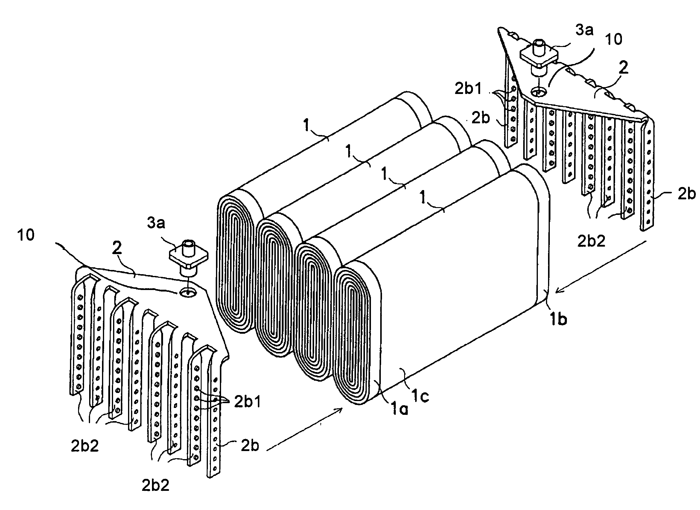
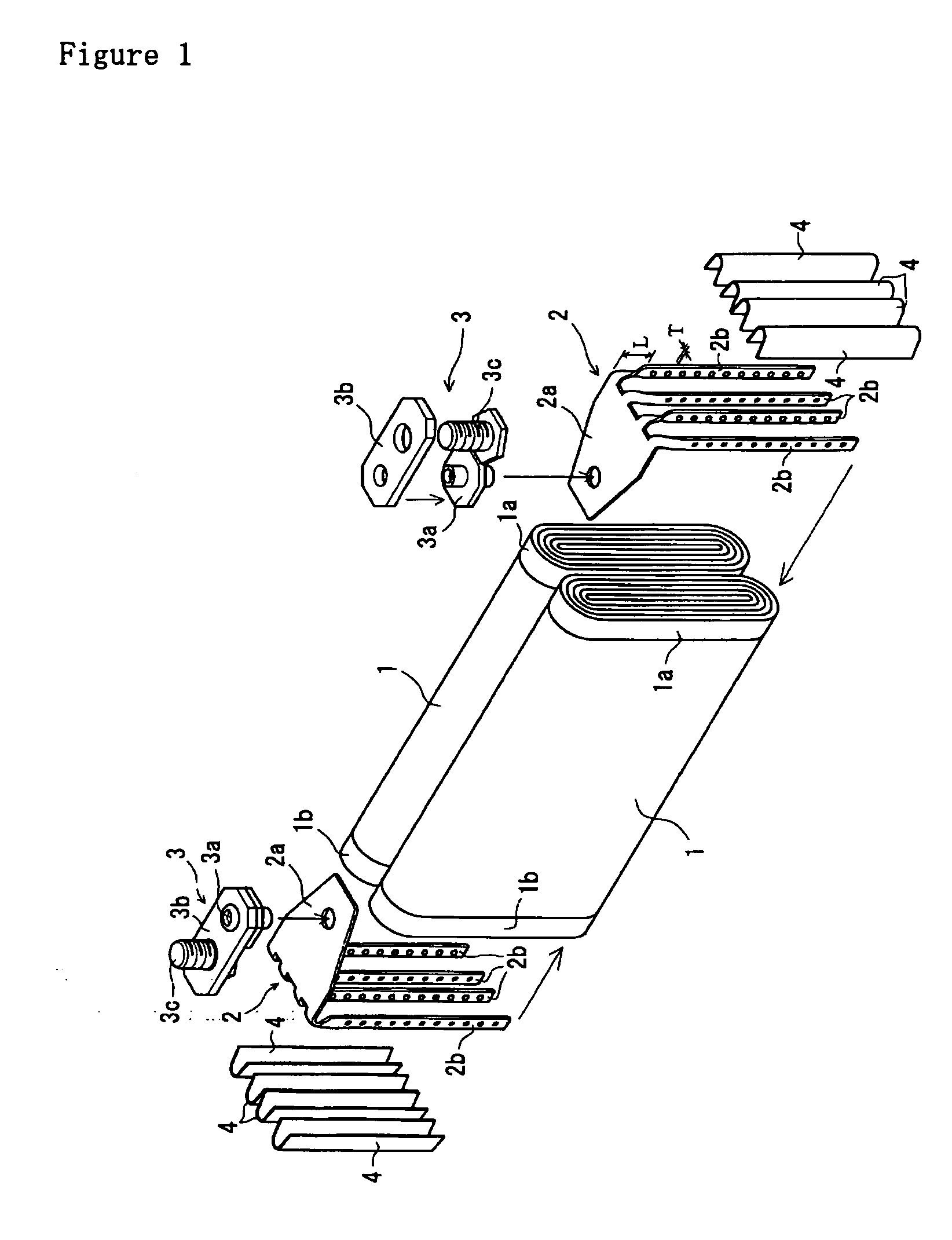
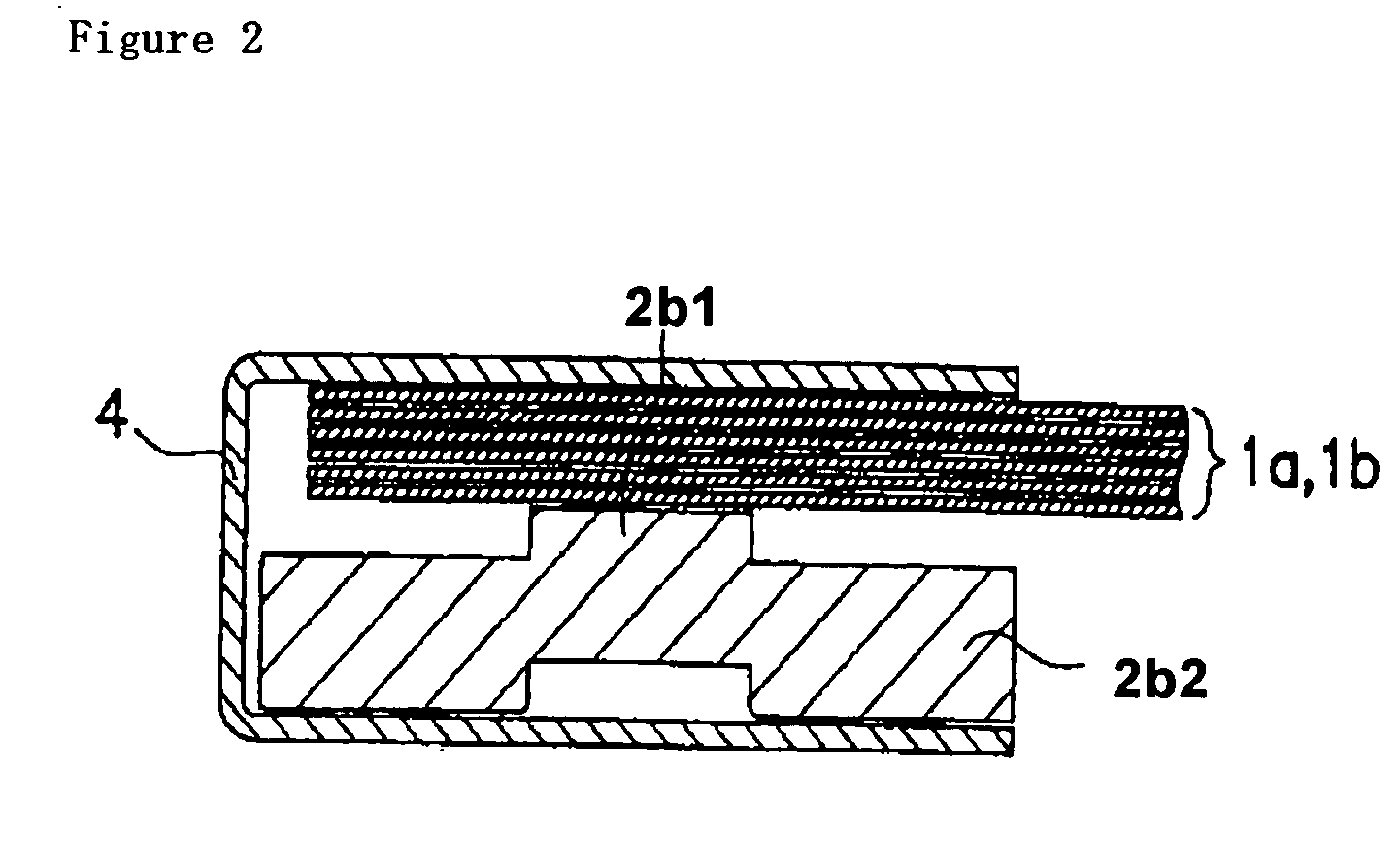
[0034]FIG. 1 is an assembly perspective view showing an embodiment of the present invention, and FIG. 2 is a cross-section view showing a state where a connecting plate portion and an electrode are inserted in a pinching plate.

[0035] The embodiment describes a large non-aqueous electrolyte secondary battery. In this non-aqueous electrolyte secondary battery, as shown in FIG. 1, two power generating elements 1, 1 of an elliptic cylindrical shape are aligned and connected in parallel. Each power generating element 1 has the same configuration as that of the prior art, where the aluminum foil at the side-edge portions of a positive electrode 1a protrudes from one end face of the elliptic cylindrical shape and the copper foil at the side-edge portions of a negative electrode 1b protrudes from the other end face.

[0036] The above-described two power generating elements...


PUM


Abstract

The metal foil of the positive electrode 1a or the negative electrode 1b in the power generating element 1 is connected along the connecting plate portion 2b which is folded, twisted, and provided in a protruding condition from the main portion 2a of the current-collector connector 2; hence the shape of the current-collector connector 2 becomes easy to form, and a battery capable of enhancing current collection efficiency, reliability and workability can be provided.

Description

TECHNICAL FIELD [0001] The present invention relates to a battery having characteristics in current-collection structure. BACKGROUND ART [0002]FIG. 9 shows the conventional connection structure of power generating elements 1, current-collector connectors 2, and external connection terminals 3 in a non-aqueous electrolyte secondary battery. In this non-aqueous electrolyte secondary battery, two power generating elements 1 of an elliptic cylindrical shape are connected in parallel. [0003] Each power generating element 1 such as shown in FIG. 3 is configured by winding a positive electrode 1a and a negative electrode 1b with a separator 1c therebetween into an elliptic cylindrical shape. In the positive electrode 1a, the surface of a strip aluminum foil 1d to be used as an electrode substrate is supported with a positive active material; and in the negative electrode 1b, the surface of a strip copper foil 1e to be used as an electrode substrate is supported with a negative active mater...

Claims


Application Information

Patent Timeline
IPC IPC(8): H01M2/26H01M2/06H01M10/052H01M10/0587H01M10/36H01M50/529H01M50/541
CPCH01M2/266H01M10/0587H01M10/052Y02E60/10H01M50/54Y02P70/50
Inventor TASAI, HIROSHISUZUKI, ISAOSHIMOZONO, TAKESHIMUNENAGA, NORIYOSHIKOJIMA, TETSUZOMATSUBARA, TAKEHITO
Owner GS YUASA INT LTD
Why Eureka
Try Eureka