Snap-in float-mount electrical connector

Active Publication Date: 2006-03-09
CORNING OPTICAL COMM LLC
View PDF15 Cites 33 Cited by
  • Summary
  • Abstract
  • Description
  • Claims
  • Application Information

AI Technical Summary

Benefits of technology

[0007] It is therefore an object of the present invention to provide a connector that overcomes the disadvantages of the prior art, and

Problems solved by technology

Another disadvantage of the first prior art connector 100 is that the C-shaped retaining ring 101 is mechanically weak and may degrade the reliability of the snap-in function.
Furthermore, if the washer is pushed into the prior art spring finger basket 401 subsequent to installation, the second

Method used


Image

  • Snap-in float-mount electrical connector
  • Snap-in float-mount electrical connector
  • Snap-in float-mount electrical connector

Examples


Embodiment Construction

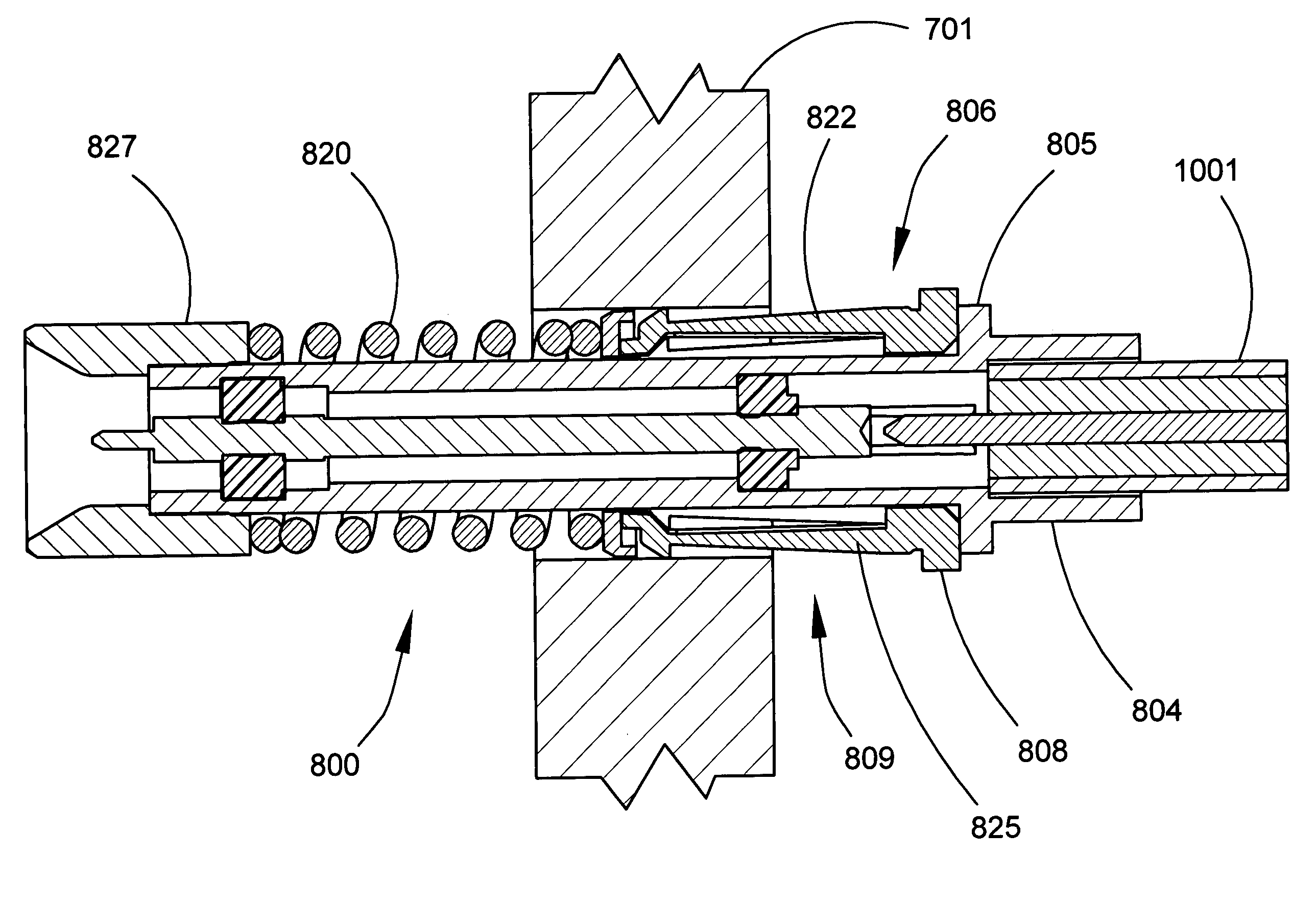
[0038] An electrical connector, or connector, constructed in accordance with the invention is shown in FIGS. 8-17, and is generally designated by reference numeral 800. FIG. 8 is a perspective view of the connector 800, which is a male plug. The connector 800 is intended to be manually inserted into a mounting hole of a panel, such as the panel 701, and retained in the mounting hole by a press-fit. The panel 701 usually has a plurality of mounting holes (typically four to twenty). The connector has an interface end, or front end 801, and a cable end, or back end 803. A push-on style interface at the front end 801 of the connector 800 mates with a mating connector (not shown), which is a female jack. The back end 803 of the connector 800 accepts an end of a coaxial cable 1001 (see FIG. 10). The connector 800 comprises a body 804 having a shape of an elongate, approximately cylindrical shaped tube extending from the back end 803 to near the front end 801 of the connector 800. The body...


PUM


Abstract

An electrical connector (800) for mounting in a mounting hole includes a body (804) and a mounting mechanism. The mounting mechanism includes a spring finger basket (806) that includes a base portion (808) and a plurality of spring fingers (809). Each spring finger (821-826) is commonly connected at the base portion and has a tip (812) at a free end opposite the base portion. The base portion is attached to an outer surface of the body adjacent to a flange (805) in the outer surface. The tip of each spring finger is spaced apart from the body. An end cap (818) is attached to the outer surface of the body. The end cap has an outer lip (819) limiting outward radial movement and permitting inward radial movement of the tip of each spring finger during radial movement of the body with respect to the mounting mechanism. A coil spring (404) is attached to the outer surface of the body. A shroud (827) is attached to the body adjacent to a front side of the coil spring. The mounting mechanism permits simultaneous radial and axial movement of the body relative to the mounting mechanism.

Description

BACKGROUND OF THE INVENTION [0001] 1. Field of the Invention [0002] This invention relates to electrical connectors, and more particularly to an electrical connector having a push-on style interface, which can be snapped into a mounting hole of a panel and which has axially floating contacts. [0003] 2. Description of the Related Art [0004] Coaxial cable connectors having a mounting configuration commonly known as “snap-in, float-mount” are used with push-on style interfaces such as a subminiature push-on (“SMP”) interface and a SMP-miniature (“SMPM”) interface, as described in MIL-STD-348A. A snap-in connector must easily and reliably snap into a mounting hole of a panel and lock itself in the mounting hole. A snap-in mechanism holds the connector body axially aligned so that it will be in a correct position to mate with a mating connector. The snap-in function of known prior art connectors is accomplished by one of several different mechanisms. A snap-in, float-mount connector has ...

Claims


Application Information

Patent Timeline
IPC IPC(8): H01R13/62
CPCH01R9/0527H01R13/743H01R13/6315
Inventor KOOIMAN, JOHN A.
Owner CORNING OPTICAL COMM LLC
Why Eureka
Try Eureka