Transmit diversity fo base stations

a technology of base stations and diversity, applied in diversity/multi-antenna systems, modulation, electromagnetic wave modulation, etc., can solve problems such as inability to achieve net performance benefits, complex operation of conversion of existing base stations to support transmit diversity, and planning difficulties

Inactive Publication Date: 2006-03-09
CELLETRA
View PDF18 Cites 79 Cited by
  • Summary
  • Abstract
  • Description
  • Claims
  • Application Information

AI Technical Summary

Benefits of technology

[0028] Preferably, said passive antenna comprises at least two antenna elements, thereby to provide receive space diversity capability.

Problems solved by technology

Without such processing there may not be any net performance benefit under certain conditions e.g., slow-moving or stationary subscriber units.
If the use of two separate transmit antennas and two separate receive antennas per Sector are being contemplated, however, planning difficulties can arise.
However, despite the availability of a duplexer, and despite most base stations having the necessary second antenna, conversion of the existing base stations to support transmit diversity is a complicated operation.
Entry into the base station unit itself may void warranties or otherwise reduce the responsibility levels of the manufacturer and modifications to the internal connections may be a cause of concern to the operator.
Entry into the base station is necessary because base stations do not usually provide an external baseband connection.
In addition a second r.f. modulator may be required which is expensive and wasteful of resources.
Some cellular network applications do not permit the use of active antenna array systems, or at least render such use of little or no advantage.
In such a case, RF cable losses may not be significant and use of an active antenna array system may neither be required nor desirable.
Another such example is where very high composite power is required to be transmitted and special transmit amplifier cooling arrangements are required, which may not be suitable for tower-mounted or roof-mounted active antenna array applications.
The issue remains however, of how to apply such a feature easily and cheaply to an existing base station where access to the baseband signal is not easily available.

Method used


Image

  • Transmit diversity fo base stations
  • Transmit diversity fo base stations
  • Transmit diversity fo base stations

Examples


Embodiment Construction

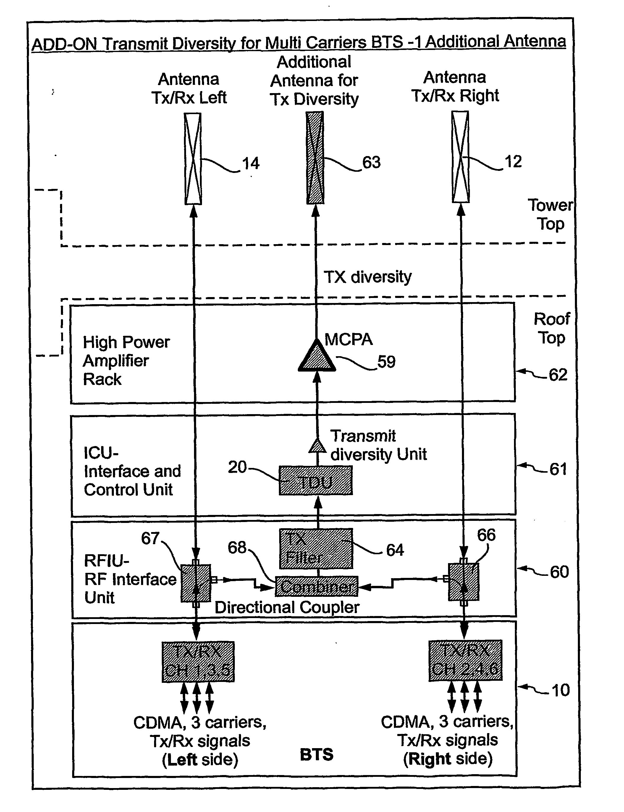
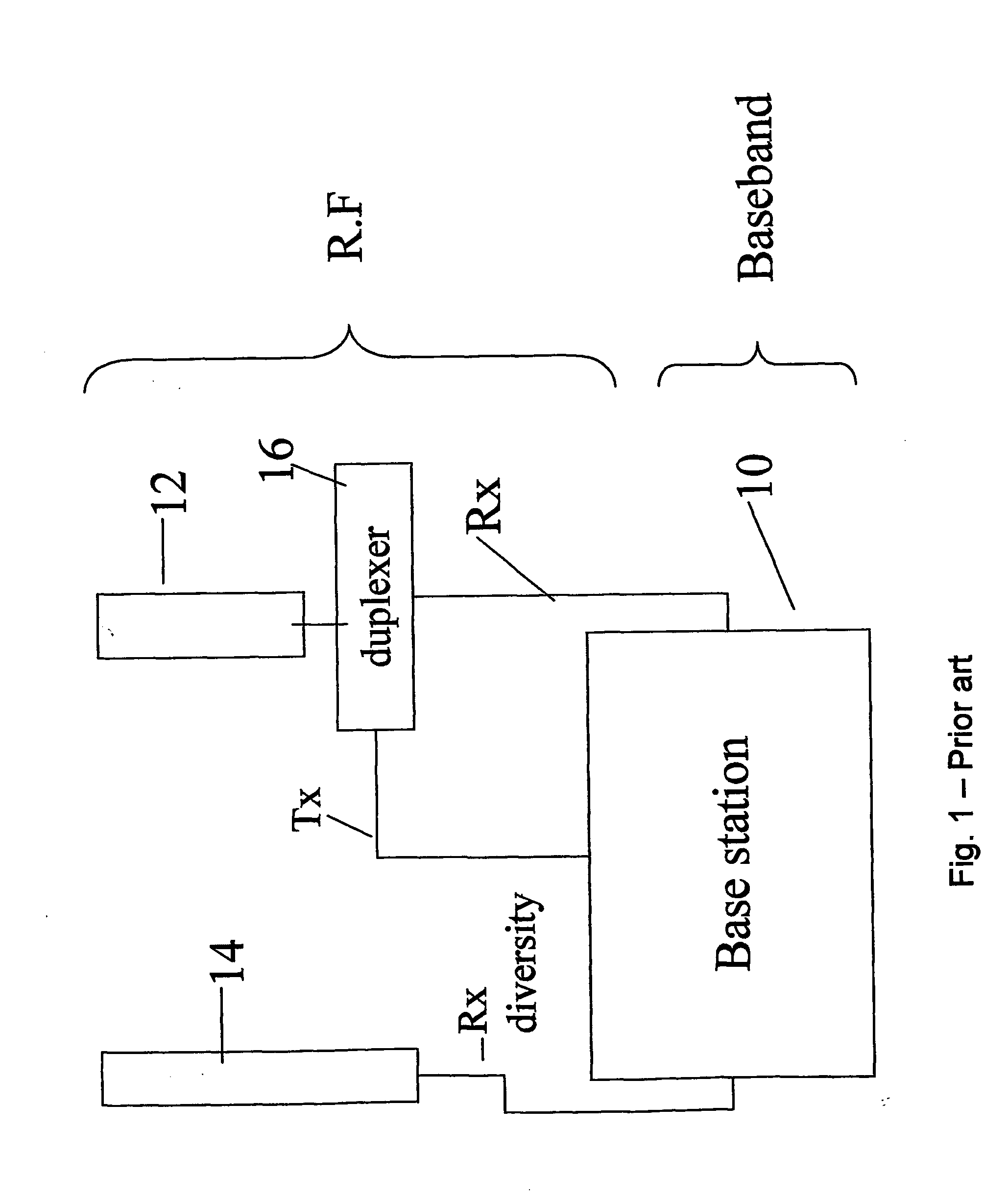
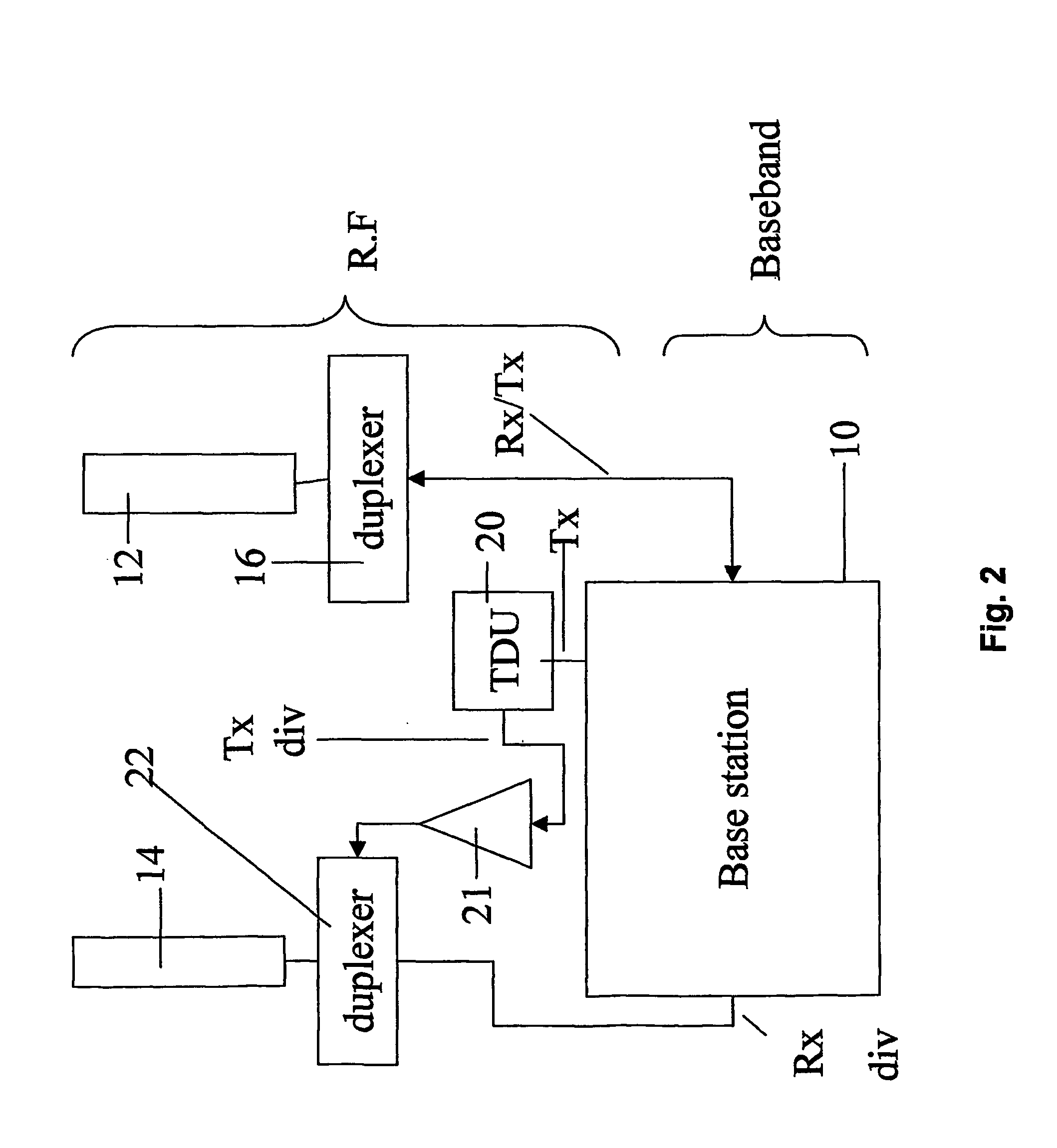
[0083] The present embodiments show a method, apparatus and system for converting a base station with a passive antenna array to support transmit diversity by applying a diversity operator to the already modulated R.F. signal. Thus the entire conversion can be carried out simply by adding components outside the base station structure at points which are easy to access. In the following a general description of the concept is followed by a series of conversion configurations for different kinds of base station. It is to be appreciated that the configurations described are not intended to be exhaustive and that the principle can be applied to other kinds of base station in ways that will be clear to the skilled person and furthermore the same principle can be applied in different ways to the kinds of base station described herein.

[0084] The principles and operation of a base station conversion kit and conversion method, and the operation of the converted base station according to the...


PUM


Abstract

A method and corresponding upgrade kit, for enhancing a base station (10) having a CDMA air interface and a passive antenna (12) with receive space diversity capability so as to provide the base station with transmit diversity capability. The method comprises attaching a radio frequency interface unit to an R.F. output of the base station to obtain a sample of a main R.F. signal, attaching a diversity unit (20) to the radio frequency interface unit to generate a transmit diversity signal, and connecting the diversity unit to the passive antenna to transmit the transmit diversity signal.

Description

FIELD AND BACKGROUND OF TH INVENTION [0001] The present invention relates to a method, system and apparatus for providing cellular base stations and the like with transmit diversity and, more particularly, but not exclusively to a method, system and apparatus which is readily applicable as an upgrade to existing base stations. [0002] Many currently installed cellular base stations include the capability to transmit and receive using multiple air interfaces, air interfaces being radio transmission signal formats used in wireless multiple access networks. Examples of such air interfaces, which are defined in cellular industry standards, include AMPS (Advanced Mobile Phone System, involving an analog FM signal employing a 30 kHz channel), CDPD (cellular digital packet data employing a 30 kHz channel), and CDMA (code division multiple access employing a 1.25 MHz channel). [0003] Many cellular base stations likewise have the capability to simultaneously receive multiple air interface sig...

Claims


Application Information

Patent Timeline
Patent Type & Authority Applications(United States)
IPC IPC(8): H04B1/02H04B7/02H03C7/02H04M1/00H04B7/06
CPCH04B7/0667H04B7/06
Inventor ARGAMAN, GIDEONLEMSON, PAULMILLER, SHMUELSHAPIRA, JOSEPH
Owner CELLETRA
Why Eureka
Try Eureka