Multi-band wireless transceiver and method of controlling the same

a wireless transceiver and multi-band technology, applied in the direction of pulse automatic control, oscillator generator, substation equipment, etc., to achieve the effect of selecting the optimal frequency band

Inactive Publication Date: 2006-03-09
NEC CORP
View PDF9 Cites 47 Cited by
  • Summary
  • Abstract
  • Description
  • Claims
  • Application Information

AI Technical Summary

Benefits of technology

[0049] In light of the above-mentioned problems in the conventional multi-band wireless transceiver, it is an object of the present invention to provide a multi-band wireless tr...

Problems solved by technology

Thus, it is unavoidable that a number of interface lines between a wireless signal processor and the central processing unit increases, and the central processing unit h...

Method used


Image

  • Multi-band wireless transceiver and method of controlling the same
  • Multi-band wireless transceiver and method of controlling the same
  • Multi-band wireless transceiver and method of controlling the same

Examples


first embodiment

[0086]FIG. 5 is a block diagram of a multi-band wireless transceiver in accordance with the first embodiment of the present invention.

[0087] Various systems such as W-CDMA, GSM, EDGE or CDMA 2000 may be applied to the multi-band wireless transceiver. In the first embodiment, it is assumed that W-CDMA is applied to the multi-band wireless transceiver. Operation for transmitting and receiving signals in each of frequency bands is identical with the operation in the multi-band wireless transceiver illustrated in FIG. 4, and hence, is not explained hereinbelow.

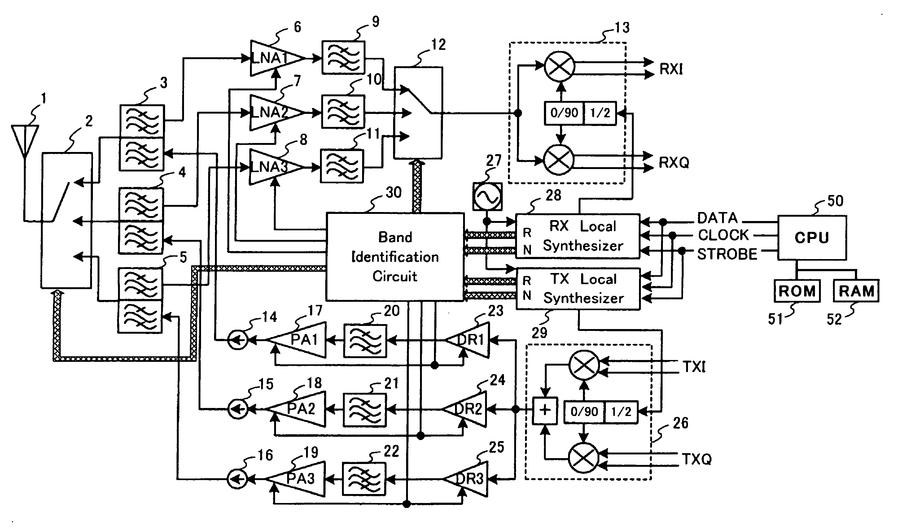
[0088] The multi-band wireless transceiver in accordance with the first embodiment is comprised of an antenna 1, an antenna switch 2, first to third duplexers 3, 4 and 5, first to third low-noise amplifiers (LNA) 6, 7 and 8, filters 9, 10 and 11, a switch 12, an orthogonal demodulator 13, first to third driver amplifiers 23, 24 and 25, filters 20, 21 and 22, first to third power amplifiers 17, 18 and 19, first to third isolators...

second embodiment

[0139]FIG. 10 is a perspective view of a mobile phone 30 to which the multi-band wireless transceiver in accordance with the first embodiment of the present invention is applied.

[0140] As illustrated in FIG. 10, the mobile phone 130 is designed to include a first body 131 and a second body 132. The first body 131 is mechanically connected at one end thereof to the second body 132 through a hinge 133 such that the first and second bodies 131 and 132 are rotatable about the hinge 133 to each other. Specifically, the first and second bodies 131 and 132 can have a first position in which they are open to each other as illustrated in FIG. 10, and a second position in which they are closed to each other.

[0141] A plurality of keys 134 are arranged on a surface 1321 of the second body 132 which surface 1321 is located internal when the first and second bodies 131 and 132 are closed to each other. A user can input data and commands into the mobile phone 130 through the keys 134.

[0142] A l...


PUM


Abstract

A multi-band wireless transceiver having a plurality of signal-processing paths, and further having a function of making wireless communication through a plurality of frequency bands by selecting one of the signal-processing paths, includes a band identification circuit for identifying a frequency band, the band identification circuit identifying a frequency band in dependence on a frequency-band information received from a controller which controls an operation of the multi-band wireless transceiver, and selecting one of the signal-processing paths in accordance with the identified frequency band.

Description

BACKGROUND OF THE INVENTION [0001] 1. Field of the Invention [0002] The invention relates to a multi-band wireless transceiver for selecting a frequency band, for instance, in a mobile phone which makes wireless communication through a plurality of frequency bands such as W-CDMA (Wideband-Code Division Multiple Access) or GSM (Global System for Mobile communication). [0003] The invention relates further to a method of such a multi-band wireless transceiver. [0004] 2. Description of the Related Art [0005] There are many mobile communication systems for a mobile phone, such as W-CDMA, GSM, EDGE (an extended system of GSM) and CDMA 2000. Each of these systems is operated through a plurality of frequency bands. A conventional mobile communication terminal such as a mobile phone is designed to operate through a single frequency band among such a plurality of frequency bands. [0006]FIG. 1 is a block diagram of a conventional wireless signal processor in a mobile communication terminal whi...

Claims


Application Information

Patent Timeline
IPC IPC(8): H04M1/00H03L7/18H03L7/183H04B1/3822H04B1/40H04W88/06
CPCH04B1/005H04B1/406H04B1/006
Inventor ICHIHARA, MASAKI
Owner NEC CORP
Why Eureka
Try Eureka