Supercharge Your Innovation With Domain-Expert AI Agents!

Gasoline fuel cell power system transient control

a fuel cell and power system technology, applied in process and machine control, electrochemical generators, instruments, etc., can solve the problems of carbon monoxide “spikes", fuel cell power system response becomes a concern, and vehicles, however, require relatively rapid load change respons

Inactive Publication Date: 2006-03-09
GM GLOBAL TECH OPERATIONS LLC
View PDF4 Cites 16 Cited by
  • Summary
  • Abstract
  • Description
  • Claims
  • Application Information

AI Technical Summary

Benefits of technology

This patent describes how to make sure that there are enough materials available for a fuel cell system during different loads or demands on the system. It does this by controlling the amount of material being fed into the system based on measurements made while the system is running.

Problems solved by technology

The technical problem addressed in this patent text is the need for a fuel cell power system that can smoothly and comprehensively respond to load transients, particularly in applications such as vehicles where rapid load change response is required. The text highlights the challenges that arise when a fuel cell power system encounters a sudden increase or decrease in demand, and the importance of finding a solution to ensure the system can maintain a steady voltage output level and effectively handle thermal and/or stoichiometric transients that accompany load transients.

Method used


Image

  • Gasoline fuel cell power system transient control
  • Gasoline fuel cell power system transient control
  • Gasoline fuel cell power system transient control

Examples


Embodiment Construction

[0017] The following description of the preferred embodiment is merely exemplary in nature and is in no way intended to limit the invention, its application, or uses.

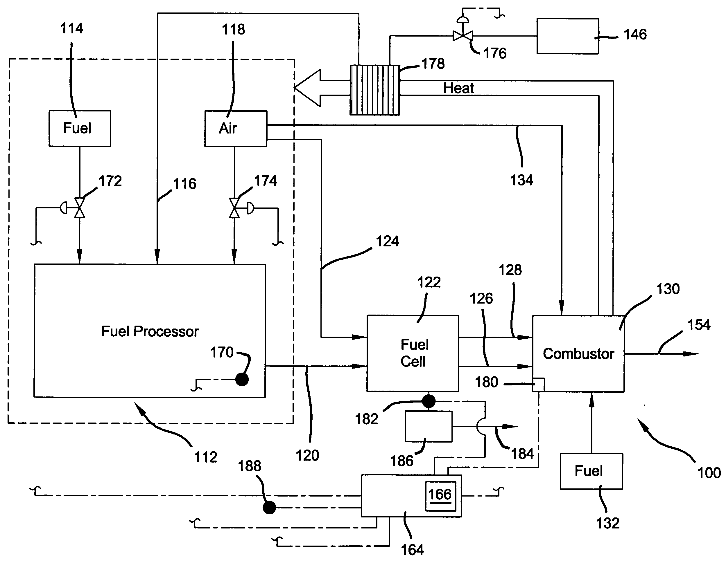
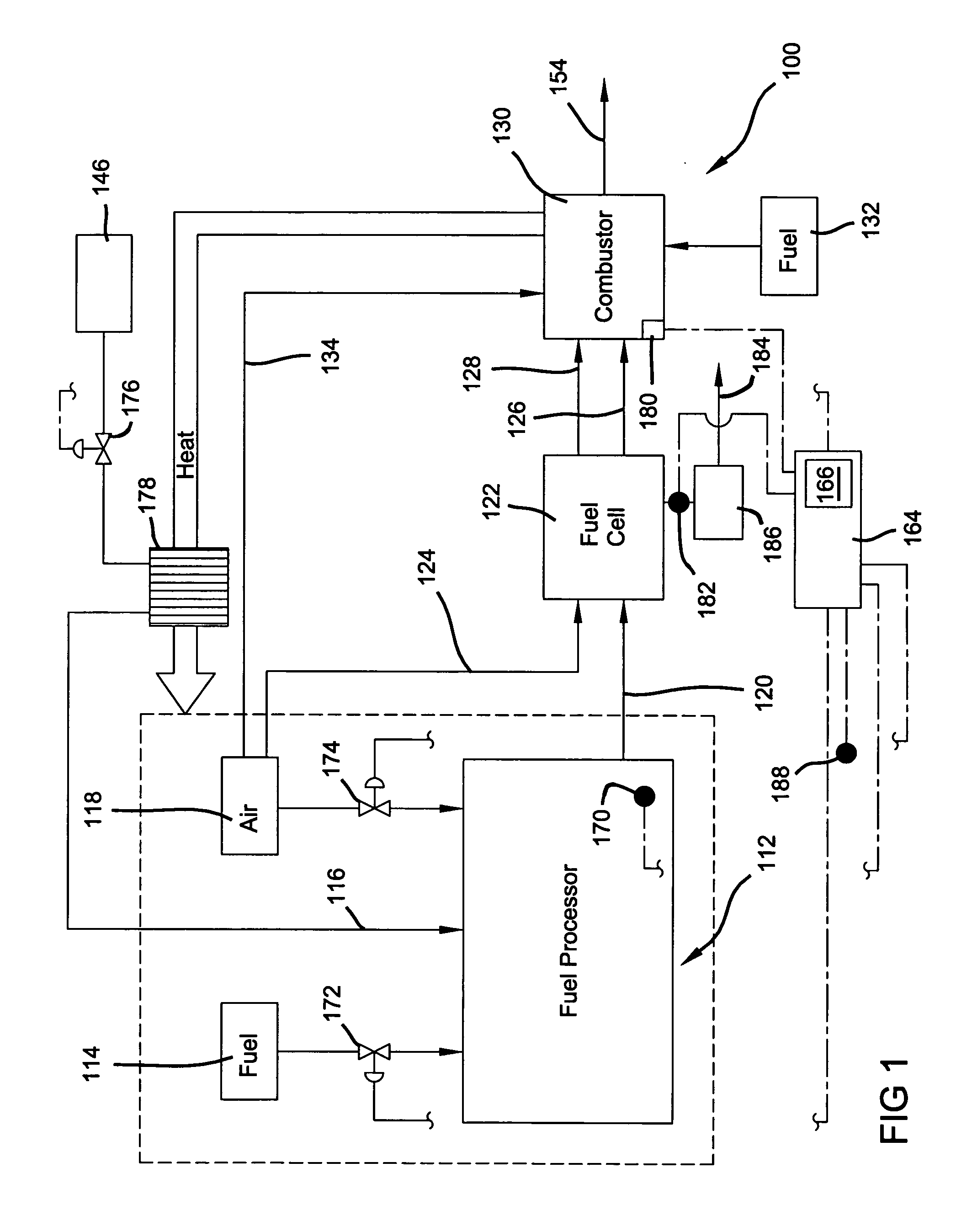
[0018] In overview, the preferred embodiment of the present invention uses a feed forward control approach to minimize the effect of water and fuel vaporizer lag once a load transient has been initiated. More specifically, the rate of change in the load command (the time derivative of the current demand) triggers a pre-determined step change adjustment to begin a pre-determined adjustment of fuel and water flows to the primary reactor of the reformer (e.g. an auto-thermal reactor also designated as the ATR). In this regard, the anode stoichiometry is promptly modified according to a predefined throughput step when a sudden change in the load command is detected. The step changes in feed settings adjust the steam to carbon (S / C) ratio and oxygen to carbon (O / C) ratio in conjunction with the general adjustments to the fe...


PUM


Abstract

A reformer fuel feed stream in fuel cell power system is catalytically reacted into a reformate stream for a fuel cell stack by adjusting fuel supply throughput according to a predefined throughput ramp when a time derivative and the current demand for the fuel cell deviates from zero by more than an acceleration threshold value. The fuel cell power system is of special value when deployed on a vehicle where the load command is derived from the accelerator pedal of the vehicle.

Description


Claims


Application Information

Patent Timeline
Owner GM GLOBAL TECH OPERATIONS LLC
Features
  • R&D
  • Intellectual Property
  • Life Sciences
  • Materials
  • Tech Scout
  • Unparalleled Data Quality
  • Higher Quality Content
  • 60% Fewer Hallucinations
Learn More