Anchoring system

a technology of anchoring system and anchoring rod, which is applied in the field of anchoring system, can solve the problems that cables, straps, chains cannot provide a rigid connection to the deck, and unnecessary damage to the deck is unacceptable to the navy

a technology of anchoring system and anchoring rod, which is applied in the field of anchoring system, can solve the problems that cables, straps, chains cannot provide a rigid connection to the deck, and unnecessary damage to the deck is unacceptable to the navy

US20060054068A1Inactive Publication Date: 2006-03-16LOCKHEED MARTIN CORP

Image

  • Anchoring system
  • Anchoring system
  • Anchoring system

Examples


Embodiment Construction

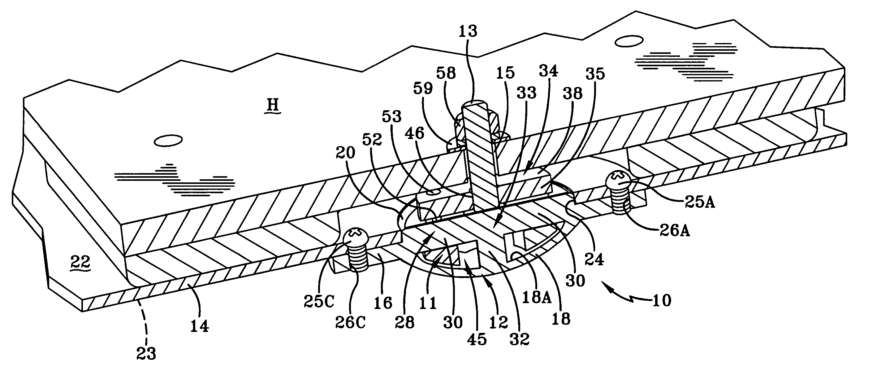
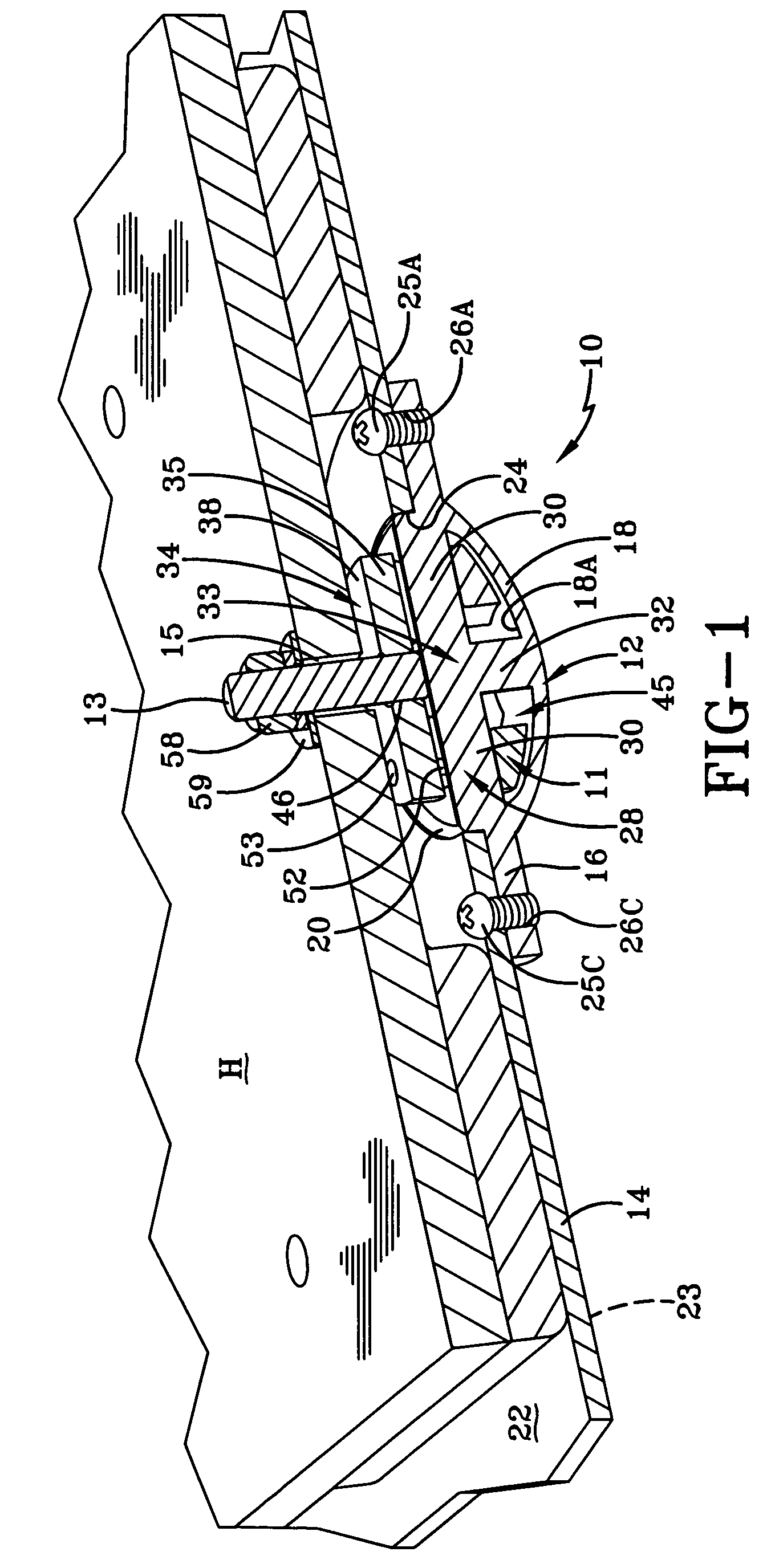
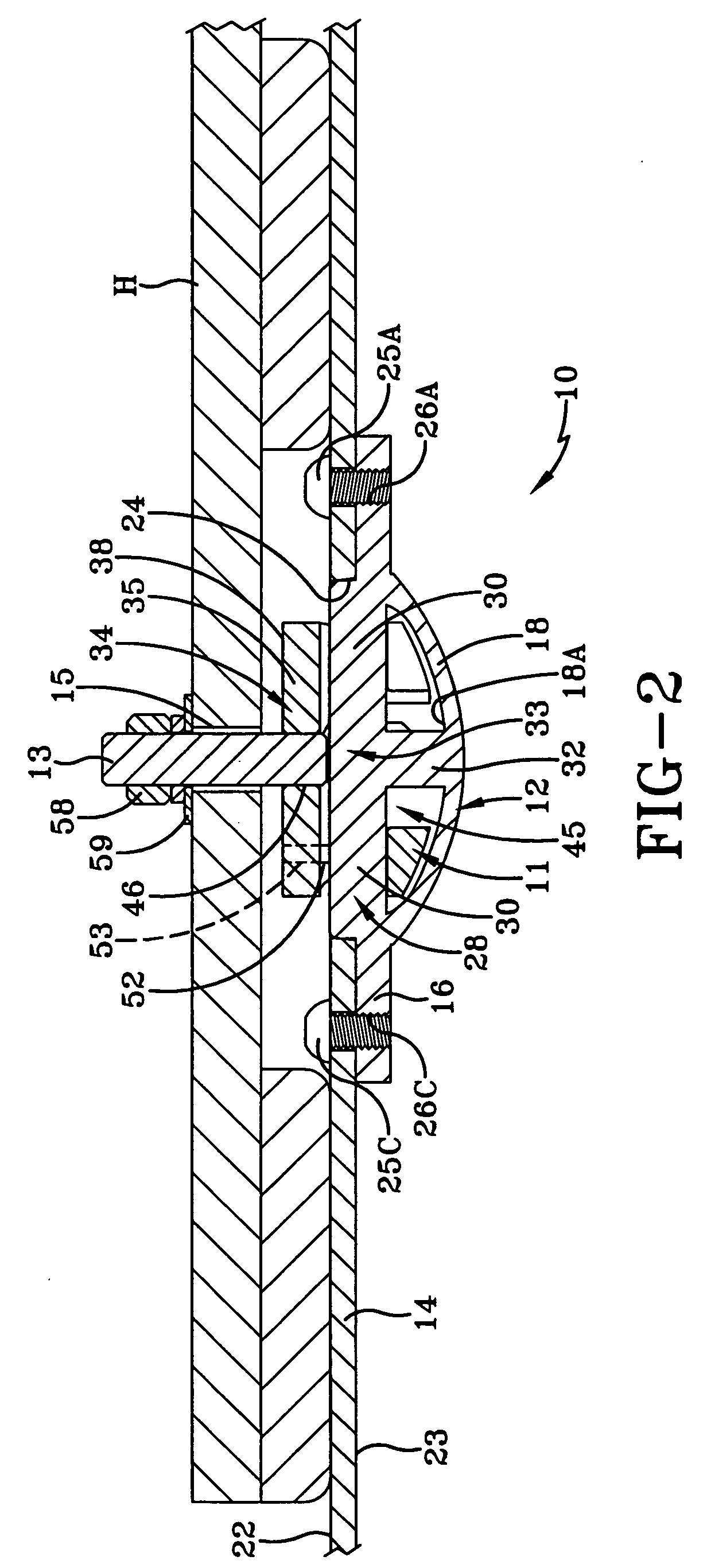
[0018] The anchoring system of the present invention is generally indicated by the numeral 10 in FIGS. 1, 2, 7A and 7B. The anchoring system employs an attachment lug 11, a tie-down 12, and a stud 13 to secure hardware H to the deck 14 of a naval vessel. For example, the tie-down 12 is attached to the deck 14, the attachment lug 11 is attached to the tie-down 12, and the stud 13 is attached to the attachment lug 11 to secure the hardware H to the deck 14. The stud 13 is used as a point of attachment, and to affect its attachment with the attachment lug 11, the stud 13 can be smoothly-surfaced or threaded. As seen best in FIGS. 1 and 2, the stud 13 extends upwardly from the attachment lug 11. The stud 13 is inserted through an aperture 15 (FIGS. 1 and 2) in the hardware H, and is capable of receiving a fastener (such as a nut). As discussed below, the fastener is received on the stud 13 to clamp the hardware H to the deck 14. Although configured for use with a naval vessel, it will b...


PUM


Abstract

An anchoring system for securing hardware having an aperture to a deck using a fastener, the anchoring system including a tie-down, an attachment lug configured to engage the tie-down, and a stud extending outwardly from the attachment lug. The tie-down includes a plate with a recess formed therein, and at least two arms traversing the recess. The attachment lug includes a base with a stud receiving aperture formed therein, and a cylindrical sidewall extending outwardly from the base. The cylindrical sidewall of the attachment lug has at least two notches extending partially therearound adapted to receive the at least two arms of the tie-down. The stud is insertable through the aperture in the hardware so that the fastener can be received on the stud to effectively clamp the hardware to the deck.

Description

CROSS REFERENCE TO RELATED APPLICATION [0001] This application claims the benefit of U.S. Provisional Application No. 60 / 558,530 filed Apr. 1, 2004, which is incorporated herein by reference.TECHNICAL FIELD [0002] The present invention relates to an anchoring system. In particular, the present invention relates to an anchoring system employing an attachment lug engaging a tie-down provided on the deck of a naval vessel. More particularly, the present invention relates to an anchoring system employing an attachment lug and a tie-down engaged by the attachment lug, the anchoring system providing a secure attachment point for hardware or equipment to the deck of a naval vessel or other platform. BACKGROUND ART [0003] Oftentimes, it is necessary to secure equipment or hardware to the deck of a naval vessel. One way to secure equipment or hardware is to provide threaded holes in the deck. However, unnecessary damage to the deck is unacceptable to the Navy. Therefore, alternatives to dril...

Claims


Application Information

Patent Timeline
16 Mar 2006
Publication
US20060054068A1
IPC
B63B21/04; B63B25/28; F16B1/00
CPC
B63B21/00; F16B21/04; F16B5/10
Inventors
FOCKLER, STEVEN G.; LEWIS, MICHAEL H.