Hydraulic shock absorber

a technology of shock absorber and shock absorber, which is applied in the direction of shock absorber, vibration damper, spring/damper, etc., can solve the problems of deformation of the response of the apparatus, likely cavitation, and unstable damping force, and achieve the effect of ensuring assembly and damping for

Inactive Publication Date: 2006-03-16
HITACHI LTD
View PDF8 Cites 27 Cited by
  • Summary
  • Abstract
  • Description
  • Claims
  • Application Information

AI Technical Summary

Benefits of technology

[0008] With the hydraulic shock absorber according to the present invention, the reservoir cartridge, the separator and the cylinder can be readily assembled to the base shell, and damping force can be generated by supplying the hydraulic fluid from the cylinder to the damping force generating mechanism through the first and second hydraulic fluid passages.

Problems solved by technology

The above-described hydraulic shock absorber having a reservoir suffers from the problem that cavitation is likely to occur because the gas in the reservoir is at low pressure.
Thus, it is likely that the damping force will become unstable, and the response of the apparatus will be degraded.

Method used


Image

  • Hydraulic shock absorber
  • Hydraulic shock absorber

Examples


Embodiment Construction

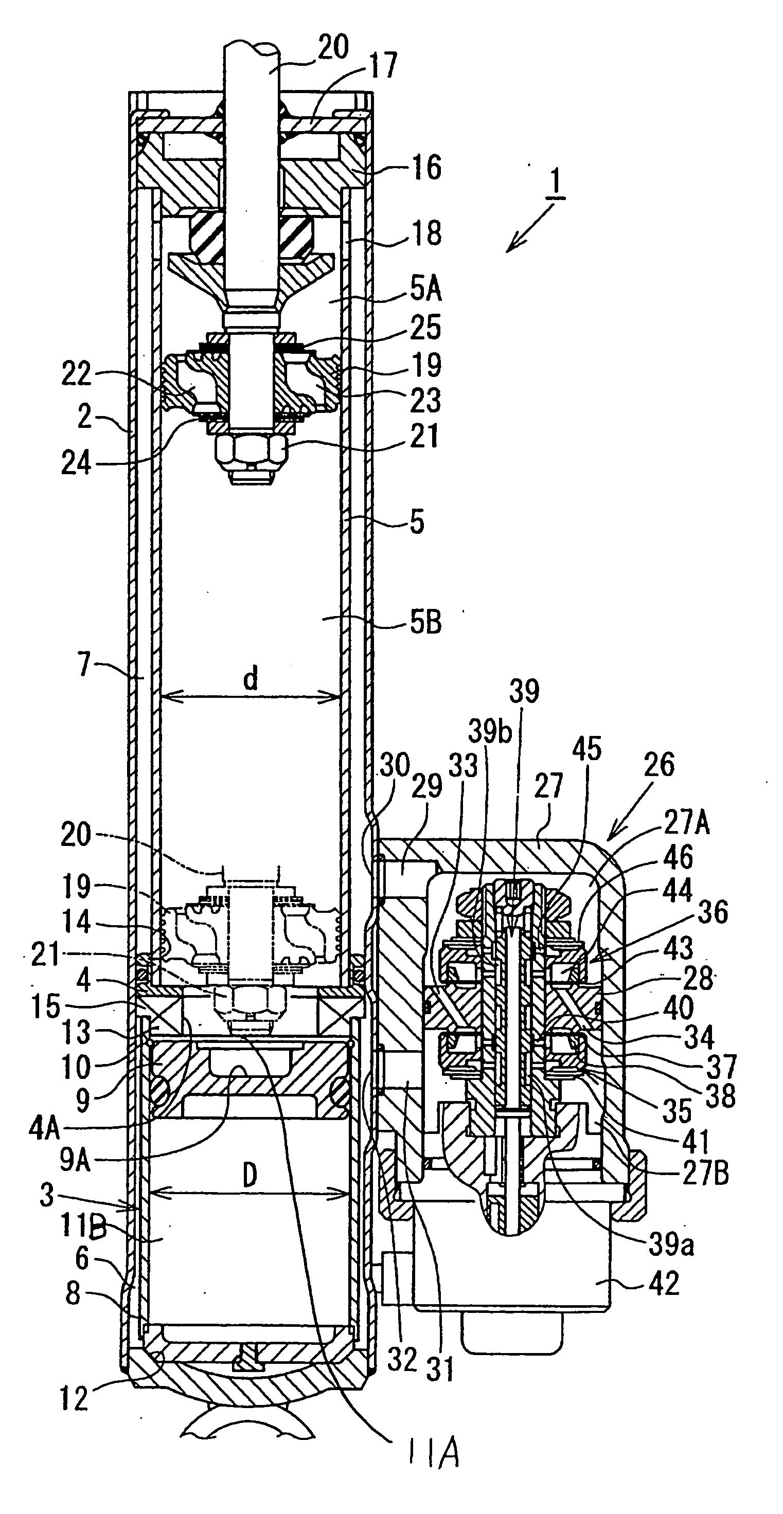
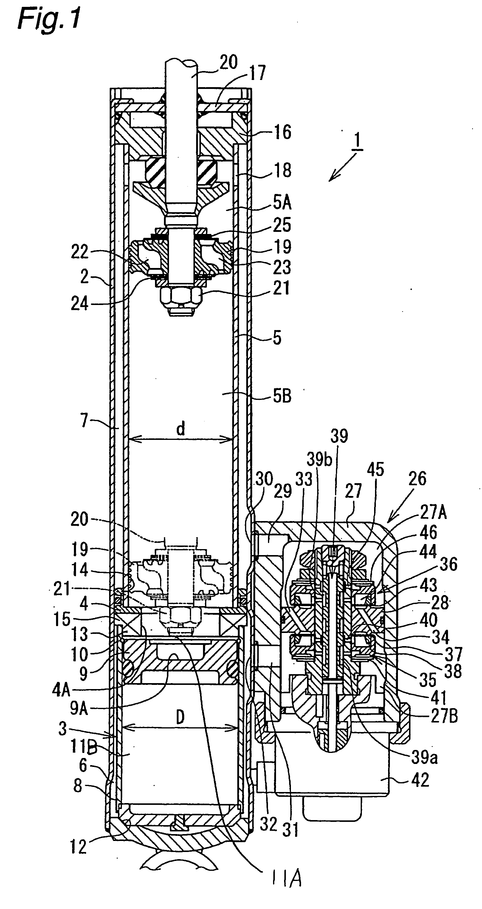
[0011] As shown in the attached FIGURE, a hydraulic shock absorber 1 according to this embodiment has a double-cylinder structure having a reservoir cartridge 3, a separator 4 and a cylinder 5 inserted into a base shell 2 having a circular cylindrical shape, one end of which is closed. An annular hydraulic fluid passage 6 (first hydraulic fluid passage) is formed between the side wall of the base shell 2 and the reservoir cartridge 3. Another annular hydraulic fluid passage 7 (second hydraulic fluid passage) is formed between the side wall of the base shell 2 and the cylinder 5. The separator 4 provides communication between the interior of the cylinder 5 and the annular hydraulic fluid passage 6. The separator 4 also cuts off communication between the hydraulic fluid passage 7, on the one hand, and, on the other, the interior of the cylinder 5 and the annular hydraulic fluid passage 6.

[0012] The reservoir cartridge 3 has a free piston 9 slidably fitted in a gas chamber casing 8 ha...


PUM


Abstract

A hydraulic shock absorber has a subassembled reservoir cartridge including a gas chamber and a free piston. The reservoir cartridge, a separator and a cylinder are inserted into a base shell, and an oil seal is secured to the base shell under application of a predetermined axial load, thereby fixing together these members in the axial direction. An annular hydraulic fluid passage is formed between the base shell and the reservoir cartridge, and another annular hydraulic fluid passage is formed between the base shell and the cylinder. A damping force generating mechanism is attached to a side of the base shell. Damping force is generated by supplying a hydraulic fluid sealed in the cylinder to the damping force generating mechanism through the annular hydraulic fluid passages. Stable damping force is obtained through pressurization by the gas chamber and through gas-liquid separation by the free piston.

Description

BACKGROUND OF THE INVENTION [0001] The present invention relates to a hydraulic shock absorber suitable for use in a suspension system of a vehicle, for example, an automobile. More particularly, the present invention relates to a hydraulic shock absorber including a reservoir tank having a hydraulic fluid chamber and a gas chamber. [0002] In general, a cylinder type hydraulic shock absorber attached to a suspension system of a vehicle, e.g. an automobile, includes a cylinder having a hydraulic fluid sealed therein. A piston having a piston rod connected thereto is slidably fitted in the cylinder. The flow of hydraulic fluid induced by sliding movement of the piston is controlled by a damping force generating mechanism including an orifice, a disk valve, etc., thereby generating damping force. In addition, the cylinder is connected with a reservoir having the hydraulic fluid and gas sealed therein to compensate for a volumetric change in the cylinder due to extension and contraction...

Claims


Application Information

Patent Timeline
Patent Type & Authority Applications(United States)
IPC IPC(8): F16F9/00
CPCF16F9/065F16F9/46F16F9/3485F16F9/3257
Inventor YAMAGUCHI, HIROYUKI
Owner HITACHI LTD
Why Eureka
Try Eureka