
Parts feeder

Inactive Publication Date: 2006-03-16
PANASONIC CORP
View PDF7 Cites 19 Cited by
  • Summary
  • Abstract
  • Description
  • Claims
  • Application Information

AI Technical Summary

Benefits of technology

[0007] However, the conventional component feeders have had no measures to automatically cope with the difference between the wafer feed component feeding operation and the tray feed component feeding operation as described above. This has been managed, depending on the component feeding mode as to whether or not the components are fed from the wafer feeding plate or the component feeding plate, by not operating the device for performing the expanding, the pushup device, and so on or preventing the influence of the operation, or manually replacing the constituent components of the devices by operators. This has an issue that the productive efficiency in the component feeding is significantly lowered.

Problems solved by technology

However, the conventional component feeders have had no measures to automatically cope with the difference between the wafer feed component feeding operation and the tray feed component feeding operation as described above.
This has an issue that the productive efficiency in the component feeding is significantly lowered.
There is also an issue that the above work becomes very troublesome for the operators and significantly lowers the work efficiency.
Therefore, it is necessary for each of the plates to perform the component feeding in the same feeding height position allowing the components to be fed, and a work for adjusting the height position of the support portion that supports each of the plates in the component feeder according to the component feeding mode (e.g., replacement of the component of the support portion or the like), and there is a further issue that the work efficiency is further lowered.
Moreover, maintenance of the component feeder has various issues as described later, and there is also an issue that the maintenanceability of the component feeder is not satisfactory, and efficient component feeding cannot be achieved.

Method used


Image

  • Parts feeder
  • Parts feeder
  • Parts feeder

Examples


first embodiment

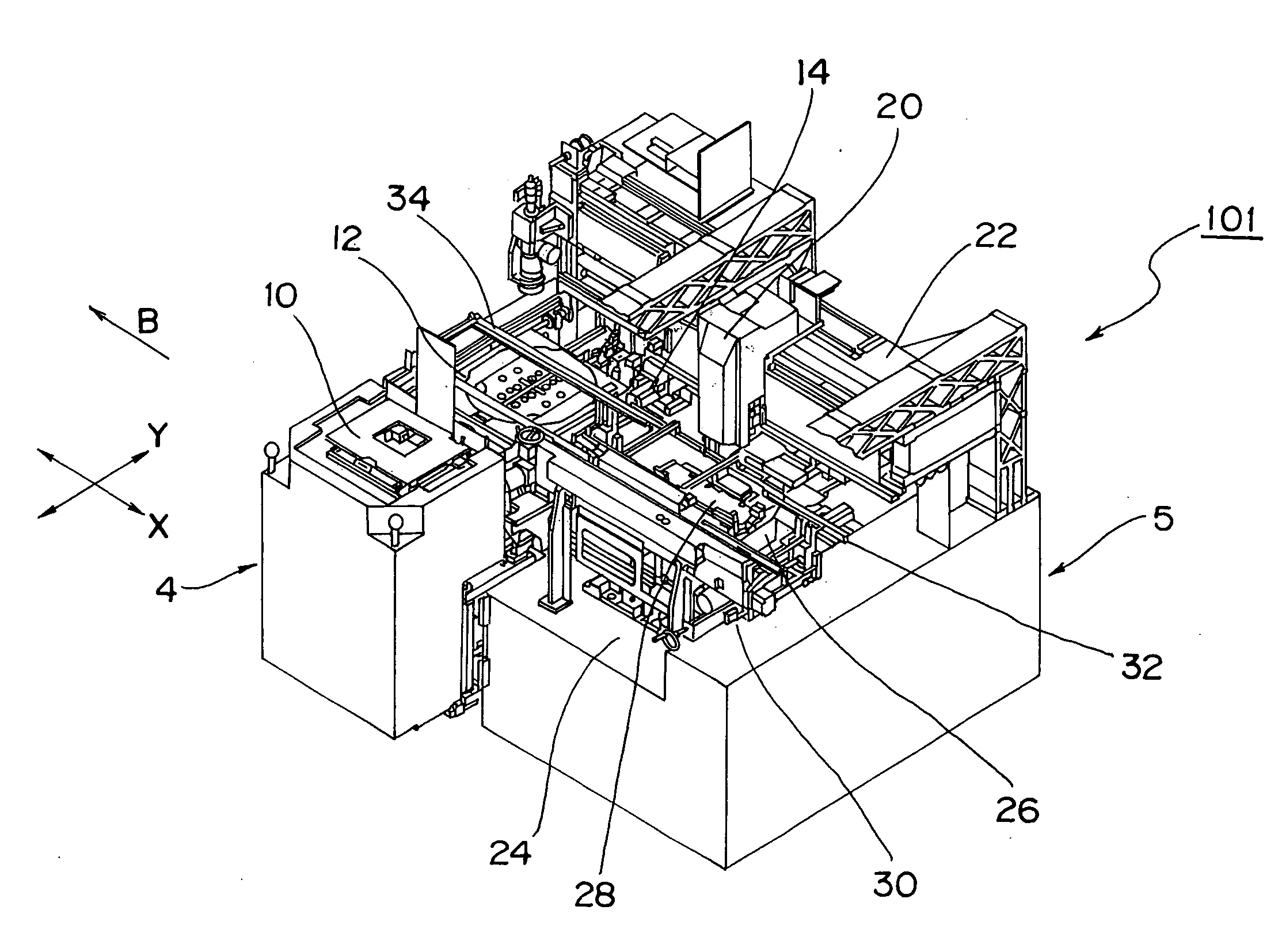
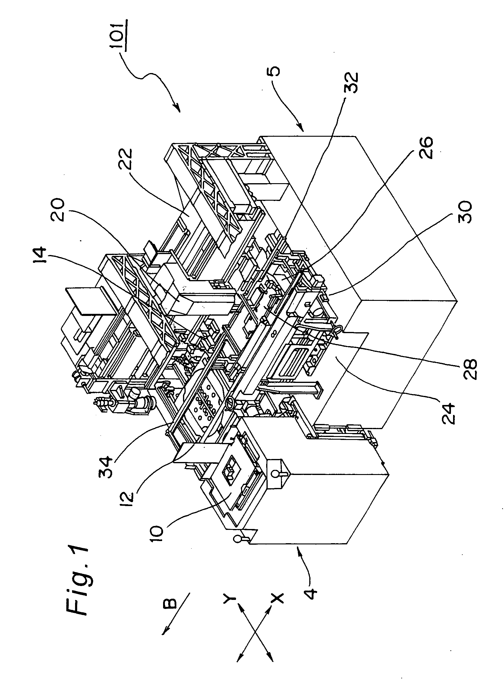
[0197]FIG. 1 shows a perspective view of an electronic component mounting apparatus 101 of one example of the component mounting apparatus that is provided with a component feeder 4 of one example of the component feeder according to the first embodiment of the present invention, for mounting components fed from the component feeder 4 on a board. Before describing the detailed structure and operation of the component feeder 4, the overall construction and operation of the electronic component mounting apparatus 101 provided with the component feeder 4 is described with reference to FIG. 1.

[0198] (Concerning Electronic Component Mounting Apparatus)

[0199] As shown in FIG. 1, the electronic component mounting apparatus 101 is an apparatus for mounting an electronic components 2 such as chip components and bare IC chips of one example of the components on a board, which is provided roughly with a component feeder 4 for receiving a plurality of electronic components 2 while allowing th...

second embodiment

[0274] The present invention is not limited to the above embodiment but allowed to be put into practice in various modes. For example, a component feeder according to the second embodiment of the present invention is described below. The component feeder of the present second embodiment has a basic construction common to that of the component feeder 4 of the first embodiment although the construction is partially varied. Therefore, in order to make the following description easy to understand, the same constituents as those of the component feeder 4 of the first embodiment are denoted by same reference numerals.

[0275] In the component feeder 204 shown in FIG. 24, the lifter unit 10 is provided with a magazine cassette 250, for receiving in mixture a plurality of wafer feeding plates and a plurality of tray feeding plates. The magazine cassette 250 has sidewall portions 250a that are opposed to each other in a direction perpendicular to the plate discharge direction C as in the firs...

third embodiment

[0303] Next, a component feeder according to the third embodiment of the present invention is described below. The component feeder of the present third embodiment has a construction common to that of the component feeder 4 of the first embodiment although the construction is partially varied as follows. Therefore, in order to make the following description easy to understand, the same constituents as those of the component feeder 4 of the first embodiment are denoted by the same reference numerals.

[0304] Before describing the component feeder of the present third embodiment, several issues that possibly occur in making random access to each of the plates 6 in the component feeder 4 of the first embodiment are described.

[0305] First, as shown in the perspective view of the component feeder 4 of FIG. 2, when each plate 6 received in the magazine cassette 50 is discharged and moved while being held by the plate moving device 40 and placed on the plate placing device 12, it is someti...


PUM


Abstract

According to the type of the plate placed in a plate placing device of a component feeder, appropriate holding operation and expanding operation are performed selectively and automatically according to the type of the plate by regulating the lowered position of a plate pressurizing member for the tray feeding plate to securely hold the plate and performing wafer expanding while securely holding the wafer feeding plate by releasing the regulation of the lowered position for the wafer feeding plate.

Description

TECHNICAL FIELD [0001] The present invention relates to a component feeder that employs a wafer feeding plate on which a wafer where a plurality of wafer feed components are arranged is placed and a tray feeding plate on which a component feeding tray where a plurality of tray feed components are arranged is placed, of components to be mounted, on a board and feeds the wafer feed components and the tray feed components to the mounting section of a component mounting apparatus while allowing the components to be mounted. BACKGROUND ART [0002] Conventionally, either one of the wafer feeding plate on which a wafer where a plurality of wafer feed components are arranged is placed and the tray feeding plate on which a component feeding tray where a plurality of tray feed components are arranged is placed, of the components to be mounted on a board, is selectively received in such a component feeder, and the wafer feeding plate or the tray feeding plate is discharged to feed the wafer fee...

Claims


Application Information

Patent Timeline
IPC IPC(8): B23Q15/00H01L21/00
CPCH01L21/67144H01L21/67132H01L21/50H01L21/02
Inventor NARITA, SHORIKIHATA, KANJIHIRATA, SHUICHISHIDA, SATOSHINAKAO, MAMORU
Owner PANASONIC CORP
Features
  • Generate Ideas
  • Intellectual Property
  • Life Sciences
  • Materials
  • Tech Scout
  • Unparalleled Data Quality
  • Higher Quality Content
  • 60% Fewer Hallucinations
Learn More