Ice dam removal system

a technology of ice dams and ice dams, which is applied in the field of ice dam removal systems, can solve the problems of forming ice dams, significant damage to inner wall structures, and damage to multiplying, and achieves the effect of fast action

a technology of ice dams and ice dams, which is applied in the field of ice dam removal systems, can solve the problems of forming ice dams, significant damage to inner wall structures, and damage to multiplying, and achieves the effect of fast action

US20060054720A1Inactive Publication Date: 2006-03-16IDRS

Image

  • Ice dam removal system
  • Ice dam removal system
  • Ice dam removal system

Examples


Embodiment Construction

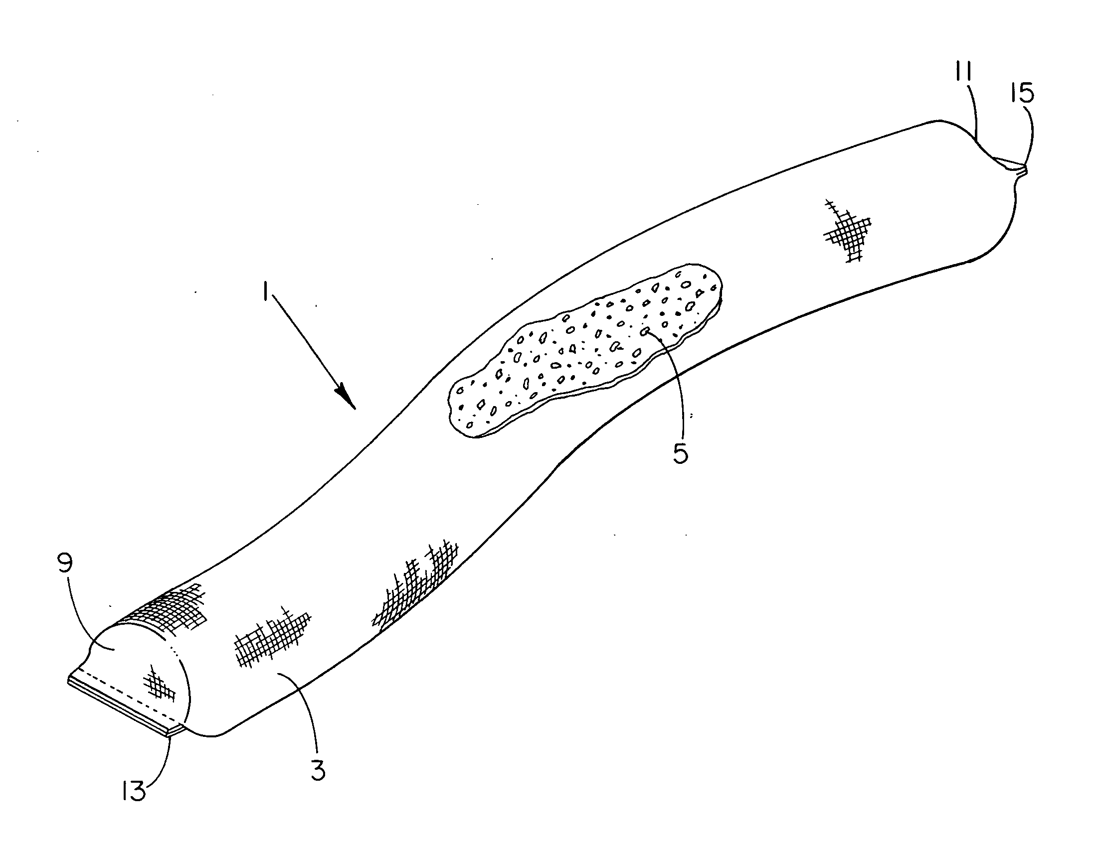
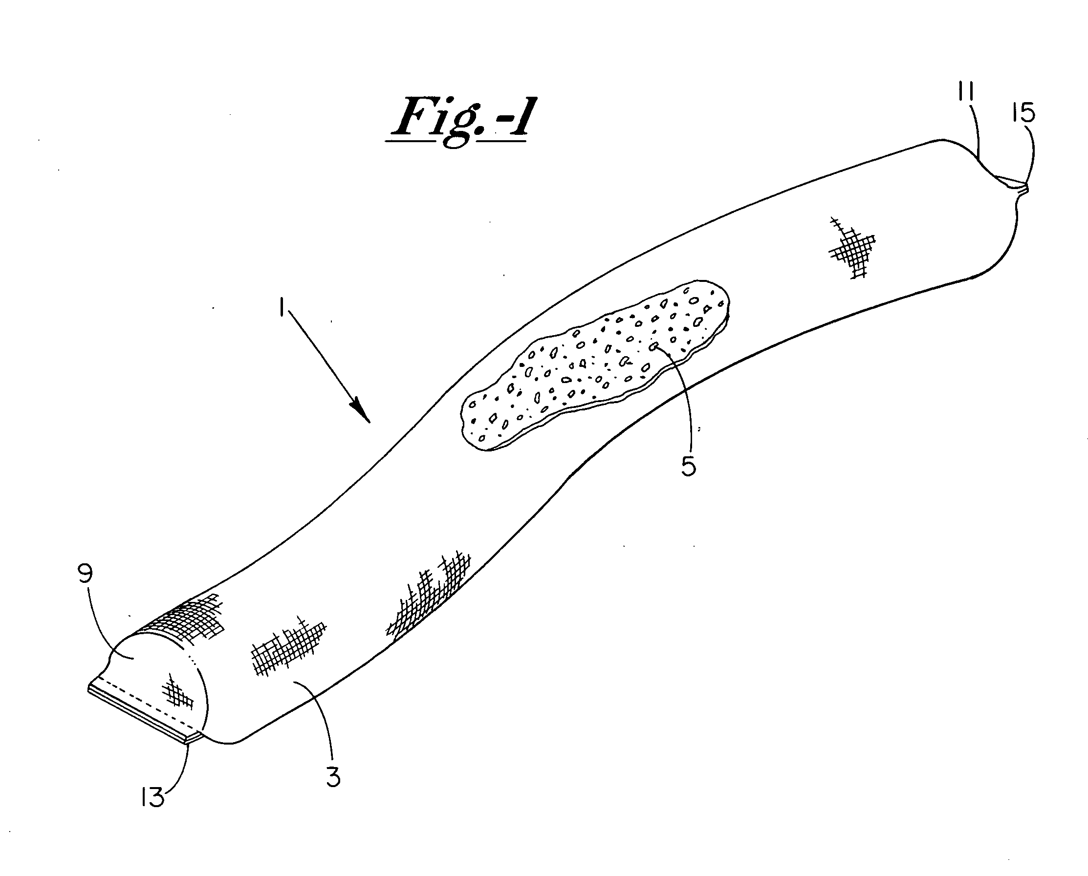
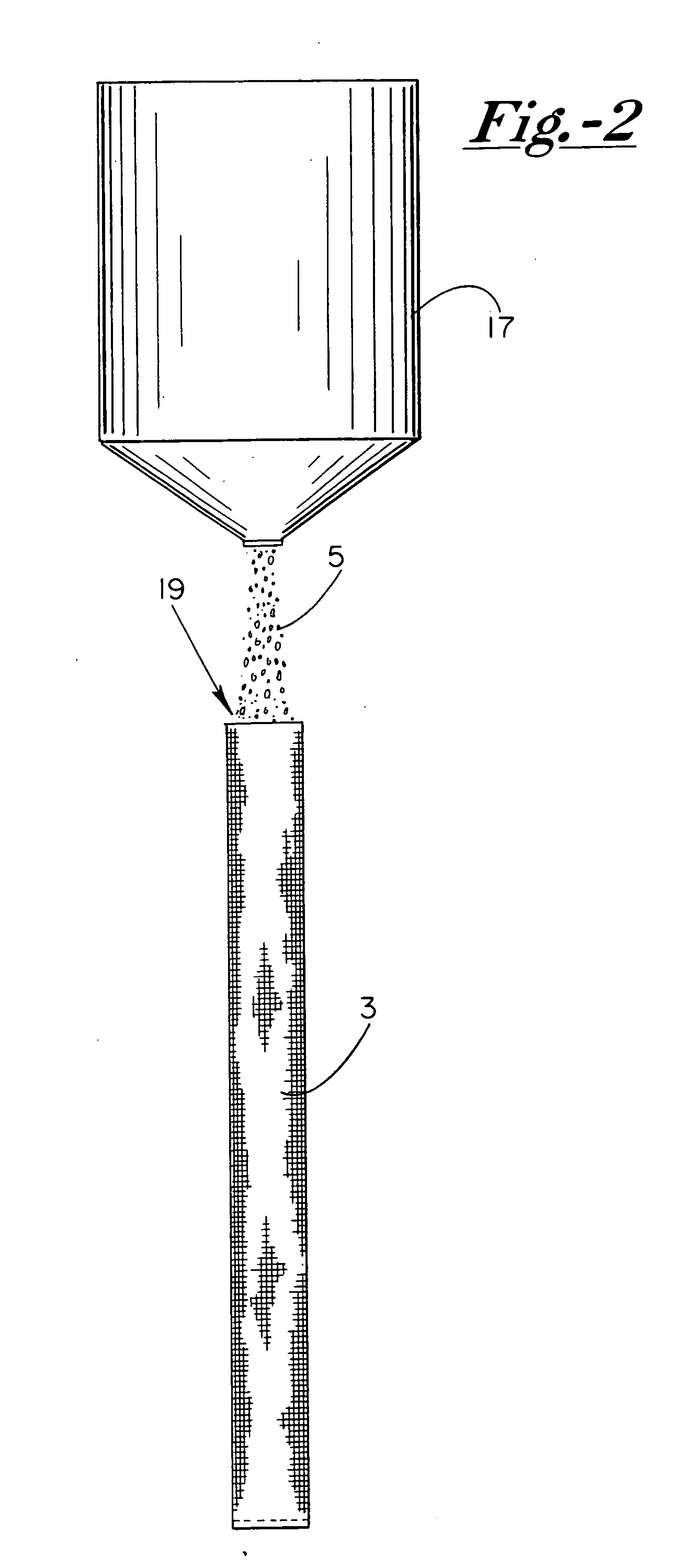
[0020] As shown in FIG. 1, our improved ice dam removal system 1 is comprised generally of an outer porous container 3 that is preferably constructed as an elongated tubular structure having a closed interior that encases our improved deicing mixture 5, which will be described in more detail hereafter. As seen, the porous container 3 is constructed of a flexible cotton or polymeric woven fabric which is designed such that the interstices defined by the interwoven strands or yarn are sufficiently small to retain the granular deicing mixture 5 therein, yet sufficiently sized to accommodate and allow water to flow freely therethrough.

[0021] In the preferred embodiment, the fabric utilized for container 3 is composed of high-tenacity monofilament polypropylene yarns, which are substantially inert to biological degradation and resist naturally encountered chemicals, alkalines, and acids. Such polypropylene yarns are woven into a stable network such that the yarns retain their relative p...


PUM

PropertyMeasurementUnit
diameteraaaaaaaaaa
lengthaaaaaaaaaa
lengthaaaaaaaaaa

Abstract

Apparatus for melting and preventing the formation of roof ice or ice dams on the upper surface of a roof which includes an elongated water-porous container having a closed interior within which a deicing mixture is contained that is composed of a heat-generating deicing agent and a corrosion-inhibiting agent. The container rests on the roof of a building above the ice dam in a transverse, obstructing position relative to the path along which water normally runs so that the water passes through the container and absorbs the deicing mixture to produce a strong deicing brine solution. The brine solution melts any ice it contacts in a medium having a temperature above −15° Fahrenheit, and inhibits corrosion of associated drains, gutters, etc. Heat-absorbing and ecologically friendly deicing agents may also be added to the mixture to prolong the deicing action and aid surrounding vegetation.

Description

BACKGROUND OF THE INVENTION [0001] Our invention is directed generally toward the field of preventing the formation of roof-ice or ice dams upon shingled rooftops and the consequential damage associated therewith. More particularly, our present invention is directed toward an improved ice melting apparatus that utilizes a generated brine solution with environmentally friendly corrosion inhibiting elements to melt and / or prevent the build-up of ice upon the roof in the event of an occurring ice dam. In this respect, the present invention constitutes a substantial improvement over methods and apparatus previously known and used, in that it operates more effectively and eliminates much of the damage caused thereby. [0002] Ice dams tend to build up on the overhang or eaves of a building adjacent the areas of roof drains and gutters. This is so because the eaves are generally less insulated and situated at the lower edge of the roofline where less heat is stored. Consequently, as heat ri...

Claims


Application Information

Patent Timeline
16 Mar 2006
Publication
US20060054720A1
IPC
A61L9/04; A24F25/00; A62C13/62; B05B7/06; A62C13/66
CPC
E04D13/103
Inventors
VALITON, JOHN R.; RETHWILL, SCOTT B.