Supercharge Your Innovation With Domain-Expert AI Agents!

Method and distributor for air-laying of fibers

a distributor and fiber technology, applied in the field of airlaying fiber distributors, can solve the problems of high production rate, high cost of finished fiber products, and relatively long synthetic fibers, and achieve the effect of saving costs and high production ra

Inactive Publication Date: 2006-03-16
OERLIKON TEXTILE GMBH & CO KG
View PDF10 Cites 3 Cited by
  • Summary
  • Abstract
  • Description
  • Claims
  • Application Information

AI Technical Summary

Benefits of technology

The present invention is related to a fiber distributor and a method of air-laying fibers that increases production capacity and reduces the formation of nits (fiber loss) during operation. The fiber distributor regulates the speed of rotation of the wings to minimize the generation of nits. The optimal speed of rotation of the wings can vary depending on the fiber structure and production parameters, and the fiber distributor can self-regulate to produce non-woven webs with a minimum of fiber loss and high production rate. The invention helps to save material and reduce expenses by reducing the amount of material employed to form the non-woven webs.

Problems solved by technology

However, the relatively long synthetic fibers are especially inclined to form nits with other similar or differing types of fibers while being swept along in the air stream by the rows of wings in the fiber distributor.
Nits are small tangled bundles of fibers, which can be quite hard and difficult to open even when they are recirculated back to e.g., a hammer mill.
Since the synthetic fibers are especially costly the finished fiber product will therefore also be costly both due to the production of nits and the need to replace them with additional synthetic fibers.
In addition, it has, in practice, been necessary to reach a compromise where a plant is operated with relatively small velocities of the air stream along the rows of wings, resulting in that the capacity of the plant is far from being fully utilized.

Method used


Image

  • Method and distributor for air-laying of fibers
  • Method and distributor for air-laying of fibers
  • Method and distributor for air-laying of fibers

Examples


Embodiment Construction

[0022] The following detailed description is based on the assumption that the fibers consist of a blend of relatively short cellulose fibers and relatively long synthetic fibers.

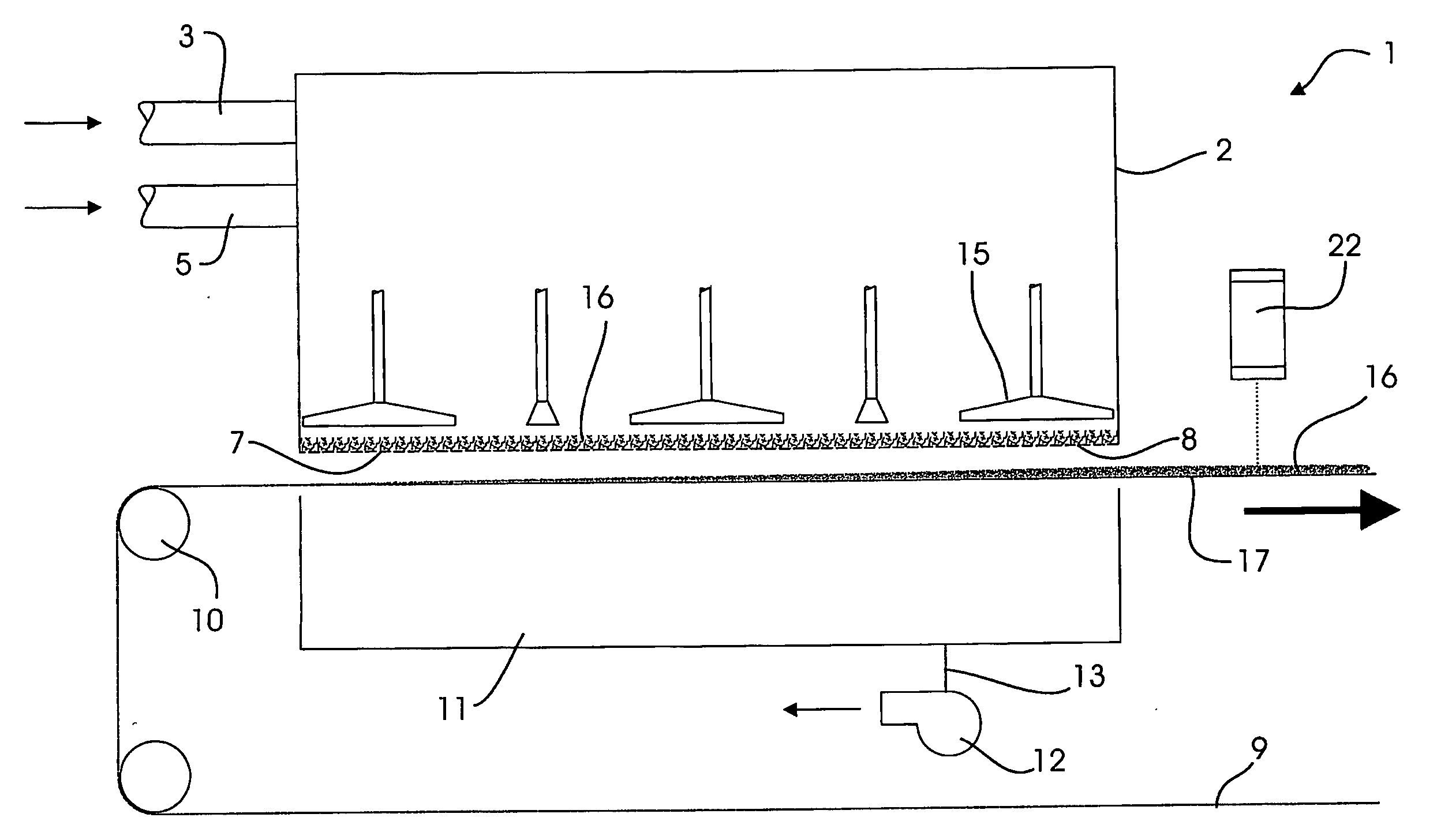
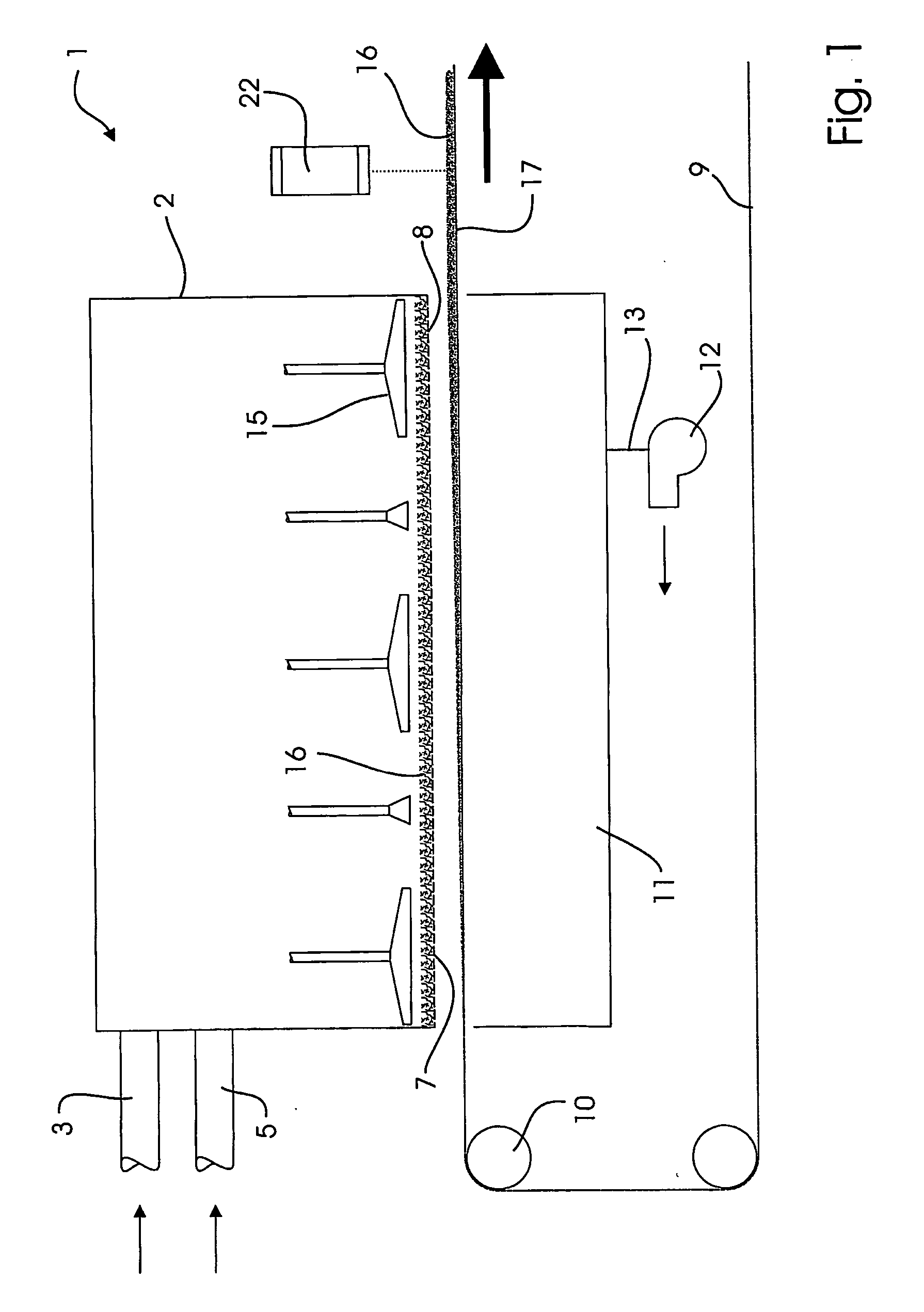
[0023] The fiber distributor 1 comprises a forming head 2 with an inlet 3 for the cellulose fibers 4 and another inlet 5 for the synthetic fibers 6. These inlets 3,5 admit the respective fibers 4,6 to enter the forming head in air streams in the direction of the arrows shown.

[0024] The forming head has a perforated bottom 7 with openings 8. Below the bottom is arranged an endless, air pervious forming wire 9 running, during production, over rolls 10 in the direction shown by the arrow. Only part of the forming wire is shown in FIGS. 1 and 2.

[0025] Below the forming wire is placed a suction box 1. An evacuating pump 12 serves for producing a negative pressure in the suction box via an air duct 13.

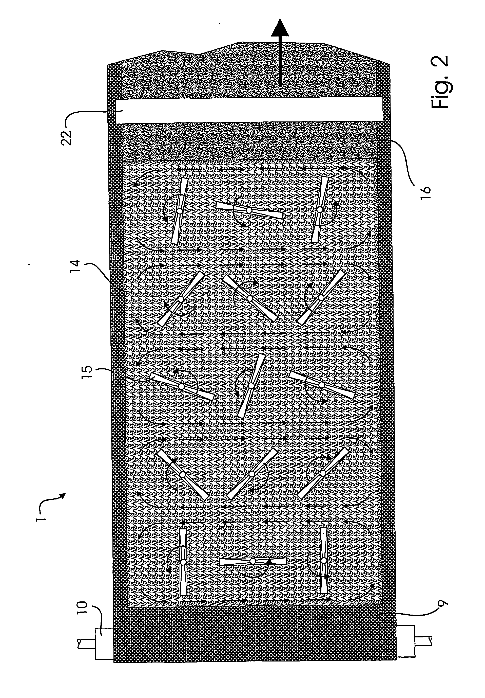
[0026] At a distance above the perforated bottom are, in this example, mounted five rows 14, each having three...


PUM

PropertyMeasurementUnit
velocityaaaaaaaaaa
velocityaaaaaaaaaa
velocityaaaaaaaaaa

Abstract

A fiber distributor is used for air-laying fibers on an endless, air pervious forming wire in a plant for producing non-woven webs. The fiber distributor includes a forming head with a perforated bottom and rows of rotatable wings situated at a distance above the bottom for during production sweeping supplied fibers along the rows of wings in an air stream before they successively leave the forming head through the openings of the perforated bottom for being deposited in a layer on the upper part of the forming wire. The fibers are, while being swept along in this way, inclined to form nits. The wings are therefore adapted to rotate with an optimal speed of rotation in an interval where the fiber's inclination to form nits changes from being lesser to being larger when the rotation speed of the wings grows. By use of the method and the fiber distributor according to the invention, it is possible to produce non-woven webs with a minimum of fiber loss in form of nits and at the same time also with an extremely high rate of production.

Description

CROSS-REFERENCE TO RELATED APPLICATIONS [0001] This application is a continuation of International application PCT / DK2004 / 000370 filed May 27, 2004, the entire content of which is expressly incorporated herein by reference thereto.BACKGROUND ART [0002] The invention relates to a method and a fiber distributor for air-laying fibers on an endless, air pervious forming wire in a plant for producing non-woven webs for us in producing absorbent core material for feminine hygiene articles, incontinence articles, diapers, table top napkins, hospital products such as bed protection sheets, wipes, or towels. [0003] The fluff, which is usually employed for products of this nature, is fluff of relatively short cellulose fibers, of relatively long synthetic fibers, or of a blend of such fibers. Other materials like e.g., SAP (Super Absorbent Powder) can be mixed into the fluff, if desired. [0004] The fiber distributor generally comprises a forming head, which is placed above the forming wire an...

Claims


Application Information

Patent Timeline
Patent Type & Authority Applications(United States)
IPC IPC(8): D04H1/70D04H1/425D04H1/72D04H1/732
CPCD04H1/425D04H1/732D04H1/72
Inventor ANDERSEN, JENS OLE BROCHNER
Owner OERLIKON TEXTILE GMBH & CO KG
Features
  • R&D
  • Intellectual Property
  • Life Sciences
  • Materials
  • Tech Scout
  • Unparalleled Data Quality
  • Higher Quality Content
  • 60% Fewer Hallucinations
Learn More