Seal ring

Active Publication Date: 2006-03-16
NOK CORP
View PDF12 Cites 10 Cited by
  • Summary
  • Abstract
  • Description
  • Claims
  • Application Information

AI Technical Summary

Benefits of technology

[0038] The conventional art has found it difficult to reduce the leakage sufficiently, in case the side wall face of the annular groove is sloped with respect to the groove bottom. A demand is also made for reducing the friction of the sliding rotations.

Problems solved by technology

The conventional art has found it difficult to reduce the leakage sufficiently, in case the side wall face of the annular groove is sloped with respect to the groove bottom.

Method used


Image

  • Seal ring
  • Seal ring
  • Seal ring

Examples


first embodiment

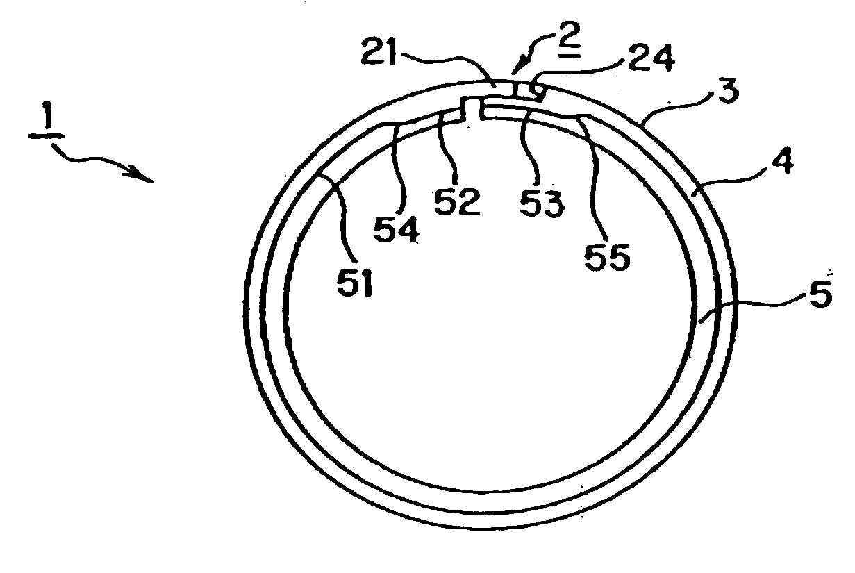
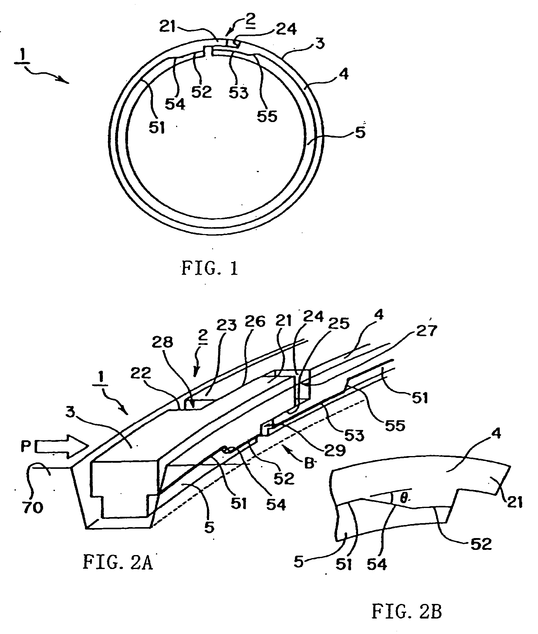
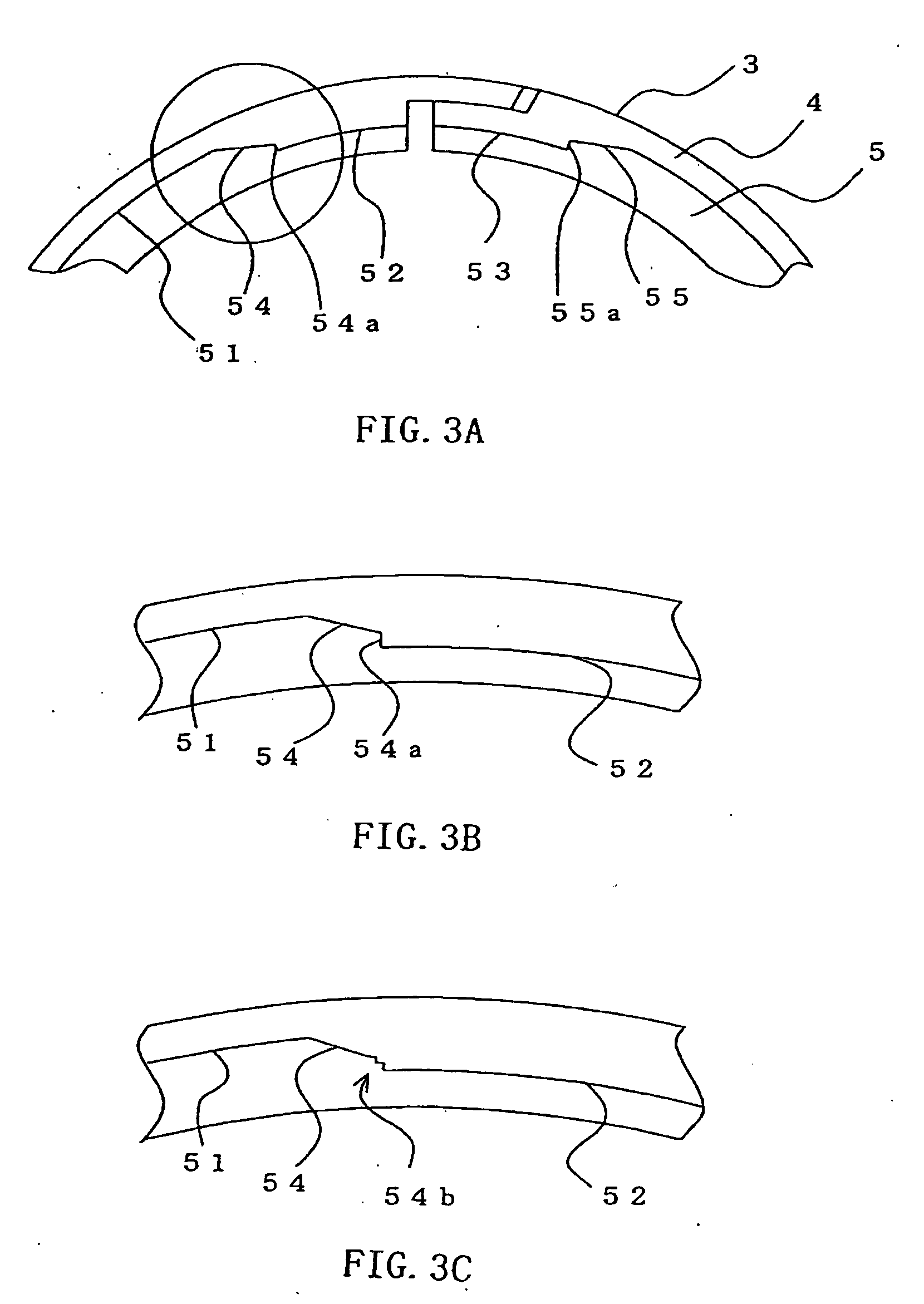
[0090] A seal ring according to a first embodiment of the invention will be described with reference to FIG. 1 to FIG. 4. FIG. 1 is a top plan view of a seal ring according to a first embodiment of the invention. FIG. 2A is a broken perspective view showing a portion of the state, in which the seal ring according to the first embodiment of the invention is mounted, and FIG. 2B is an enlarged view of a portion taken in a direction B of FIG. 2A. FIG. 3A is a portion of a top plan view showing a modification of the seal ring according to the first embodiment of the invention; FIG. 3B is an enlarged view of a portion of FIG. 3A (i.e., an encircled portion of FIG. 3A); and FIG. 3C is an enlarged view of a portion of the top plan view showing a modification of the seal ring according to the first embodiment of the invention. FIG. 4 is a schematic section showing the state, in which the seal ring according to the first embodiment of the invention is mounted.

[0091] As shown, the seal ring ...

second embodiment

[0133] A seal ring according to a second embodiment of the invention will be described with reference to FIG. 5 to FIG. 7. FIG. 5 is a top plan view of a seal ring according to a second embodiment of the invention. FIG. 6 is a broken perspective view of a portion showing the state, in which the seal ring according to the second embodiment of the invention is mounted. FIG. 7 is a schematic section showing the state, in which the seal ring according to the second embodiment of the invention is mounted.

[0134] As shown, the seal ring 1a seals the annular clearance between a housing 80 that has a bore and a shaft 70 inserted in the bore. This seal ring 1a is mounted for use in an annular groove 71 formed in the shaft 70.

[0135] The seal ring 1a is made of a resin material. The seal ring 1a is provided with a first sealing face 3a for sealing the inner circumference 81 of the bore formed in the housing 80, and a second sealing face 4a for sealing the side wall face 72.of the annular groo...

third embodiment

[0168] A seal ring according to a third embodiment of the invention will be described with reference to FIG. 8 to FIG. 10. FIG. 8 is a top plan view of the seal ring according to a third embodiment of the invention. FIG. 9 is a broken perspective view of a portion showing the state, in which the seal ring according to the third embodiment of the invention is mounted. FIG. 10 is a schematic section showing the state, in which the seal ring according to the third embodiment of the invention is mounted.

[0169] As shown, the seal ring 1b seals the annular clearance between a housing 80 that has a bore and a shaft 70 inserted in the bore. This seal ring 1b is mounted for use in an annular groove 71 formed in the shaft 70.

[0170] The seal ring 1b is made of a resin material. The seal ring 1b is provided with a first sealing face 3b for sealing the inner circumference 81 of the bore formed in the housing 80, and a second sealing face 4b for sealing the side wall face 72 of the annular groo...


PUM


Abstract

A seal ring for sealing an annular clearance between two members, which are made rotatable relative to each other. The seal ring is provided with a relief 5 throughout the circumference of a sliding face side to confront the side wall face 72 of an annular groove 71. This relief 5 is set to have a radially smaller width in the vicinity of a separate portion 2 and a radially larger width at a position apart from the separate portion 2, and the portion of the relief 5 to transit from the narrower portion to the wider portion is set to have a gradually changing width.

Description

TECHNICAL FIELD [0001] This invention relates to a seal ring for sealing an annular clearance between two members which are made rotatable relative to each other. BACKGROUND ART [0002] In the conventional art, the seal ring of this kind is used in a variety of hydraulic apparatus such as an automatic transmission for an automobile. [0003] A general seal ring will be described with reference to FIG. 11 and FIG. 12. FIG. 11 is a perspective view showing the mounted state of a seal ring according to the conventional art. FIG. 12 is a schematic section showing the mounted state of the seal ring according to the conventional art. [0004] The shown seal ring 100 seals the annular clearance between a housing 800 that has a bore and a shaft 700 inserted in the bore. This seal ring 100 is mounted for use in an annular groove 701 formed in the shaft 700. [0005] The seal ring 100 is made of a resin material. The seal ring 100 is provided with a first sealing face 100a for sealing the inner circ...

Claims


Application Information

Patent Timeline
IPC IPC(8): F16J9/12F16J9/14F16J9/20F16J15/44
CPCF16J9/14F16J15/442F16J15/441F16J9/20F16J15/16
Inventor UMETSU, KYOHEIEGUCHI, NOBUYUKI
Owner NOK CORP
Why Eureka
Try Eureka