
Imaging device having image color adjustment function

a technology of color temperature adjustment and imaging device, which is applied in the field of imaging device, can solve the problems of color temperature unevenness in the image area, and the unevenness of color temperature is also likely to occur in the same image area, and achieve the effect of suppressing the influence of color temperature unevenness and stable color reproduction of a reference subj

Inactive Publication Date: 2006-03-16
NIKON CORP
View PDF13 Cites 18 Cited by
  • Summary
  • Abstract
  • Description
  • Claims
  • Application Information

AI Technical Summary

Benefits of technology

[0011] In view of the above problems, it is therefore an object of the present invention to realize stable color reproduction of a reference subject while suppressing the influence of unevenness of color temperature in an image area.

Problems solved by technology

Therefore, if there are portions corresponding to both of direct sunlight and shadow in an image area, unevenness of the color temperature occurs in the image area.
Further, at photographing at night or inside the room, the unevenness of color temperature is also likely to occur in the same image area because different kinds of lights such as fluorescent light, bulb, sunlight coming through the window and so on are present in a mixed, complicated manner.

Method used


Image

  • Imaging device having image color adjustment function
  • Imaging device having image color adjustment function
  • Imaging device having image color adjustment function

Examples


Embodiment Construction

[0025] Hereinafter, a preferred embodiment of the present invention will be explained in detail with reference to the drawings.

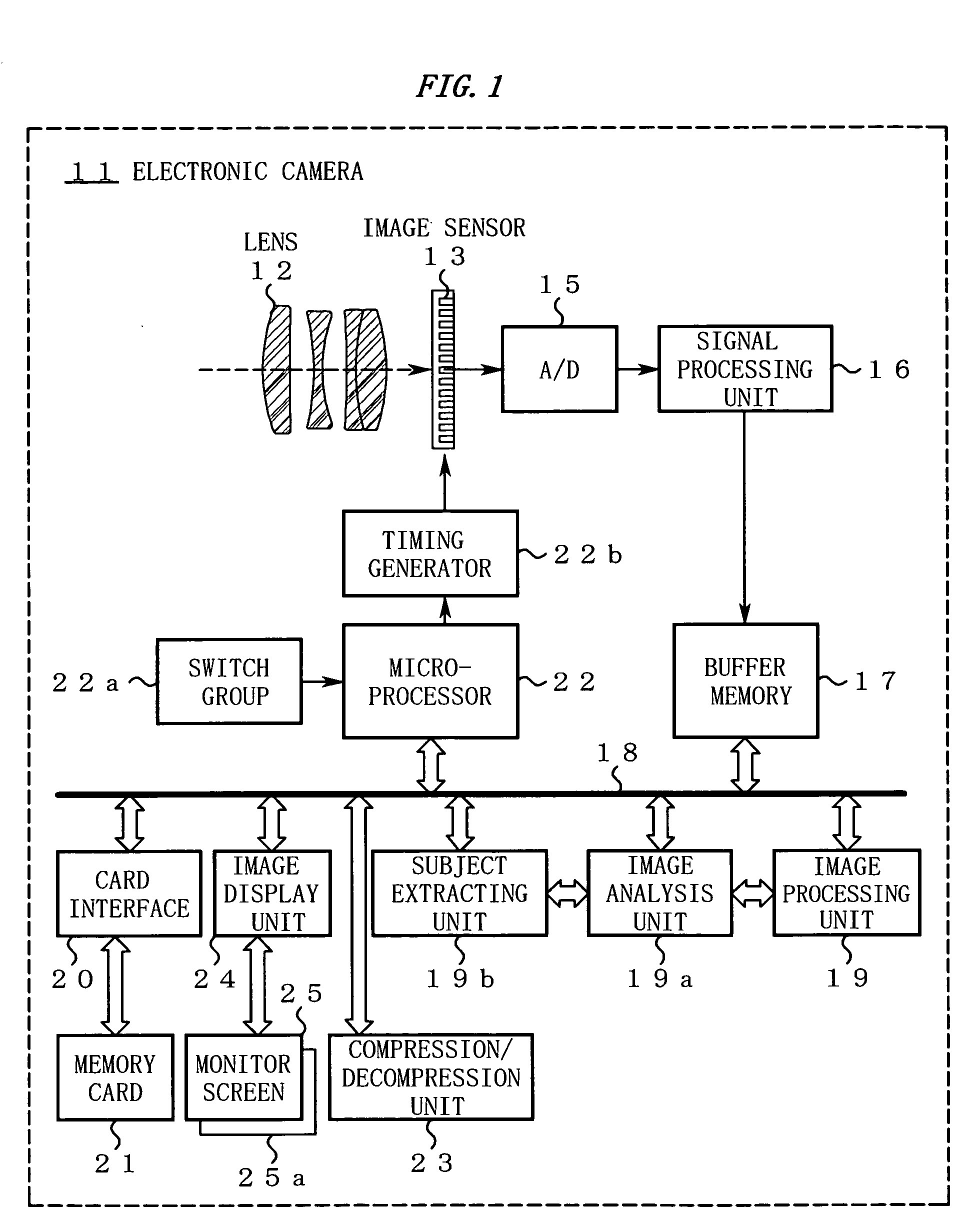
[0026]FIG. 1 is a block diagram showing an electronic camera 11 according to this embodiment.

[0027] In FIG. 1, the electronic camera 111 is equipped with a lens 12. In an image space of the lens 12, a light-receiving surface of an image sensor 13 is arranged. The operation of the image sensor 13 is controlled by an output pulse of a timing generator 22b.

[0028] An image generated by the image sensor 13 is temporarily stored in a buffer memory 17 via an A / D converting unit 15 and a signal processing unit 16.

[0029] The buffer memory 18 is connected to a bus 18. To the bus 18, an image processing unit 19, an image analysis unit 19a, a subject extracting unit 19b, a card interface 20, a microprocessor 22, a compression / decompression unit 23, and an image display unit 24 are connected.

[0030] Among these, the card interface 20 reads / writes data to / from a detac...


PUM


Abstract

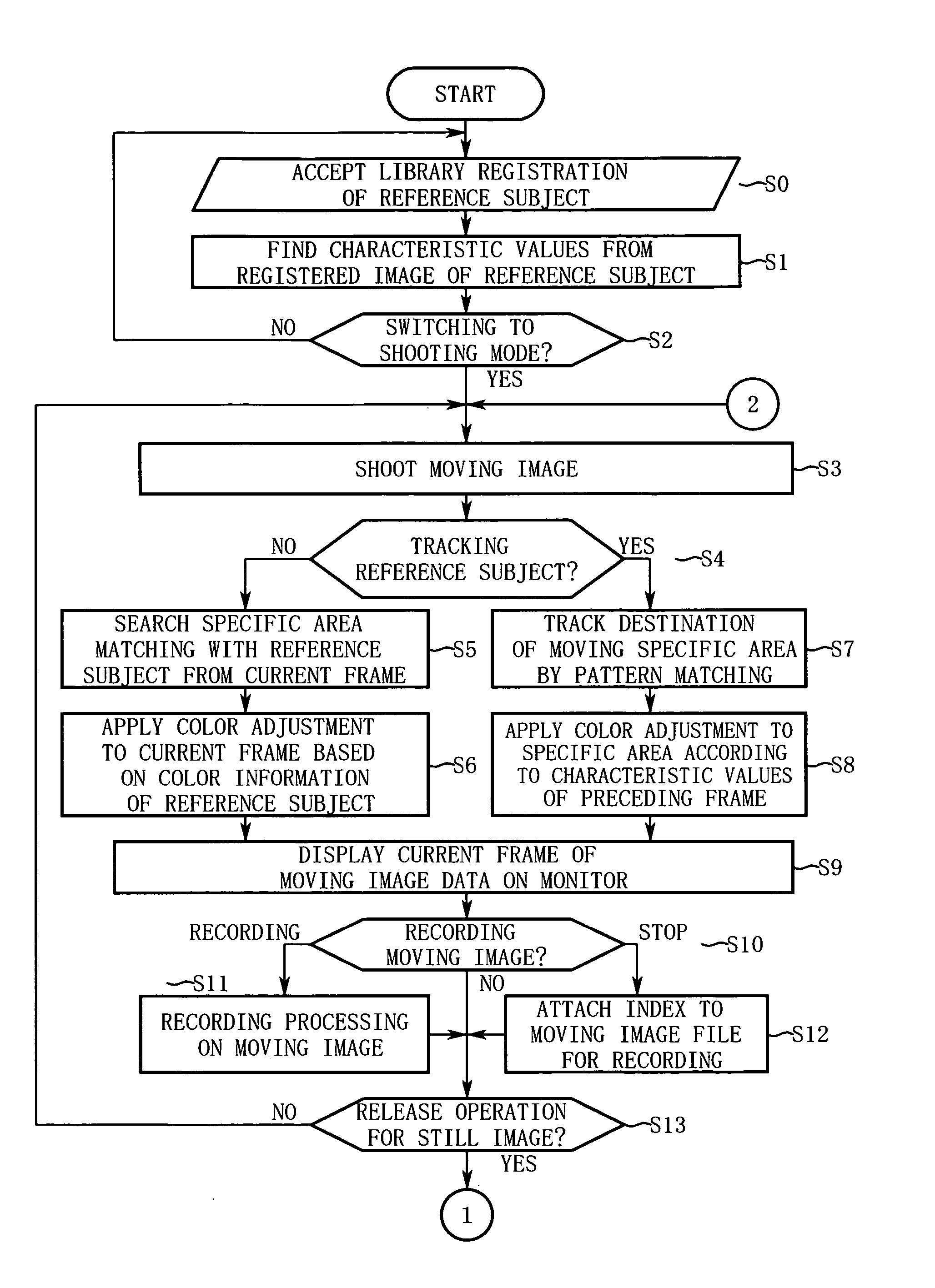
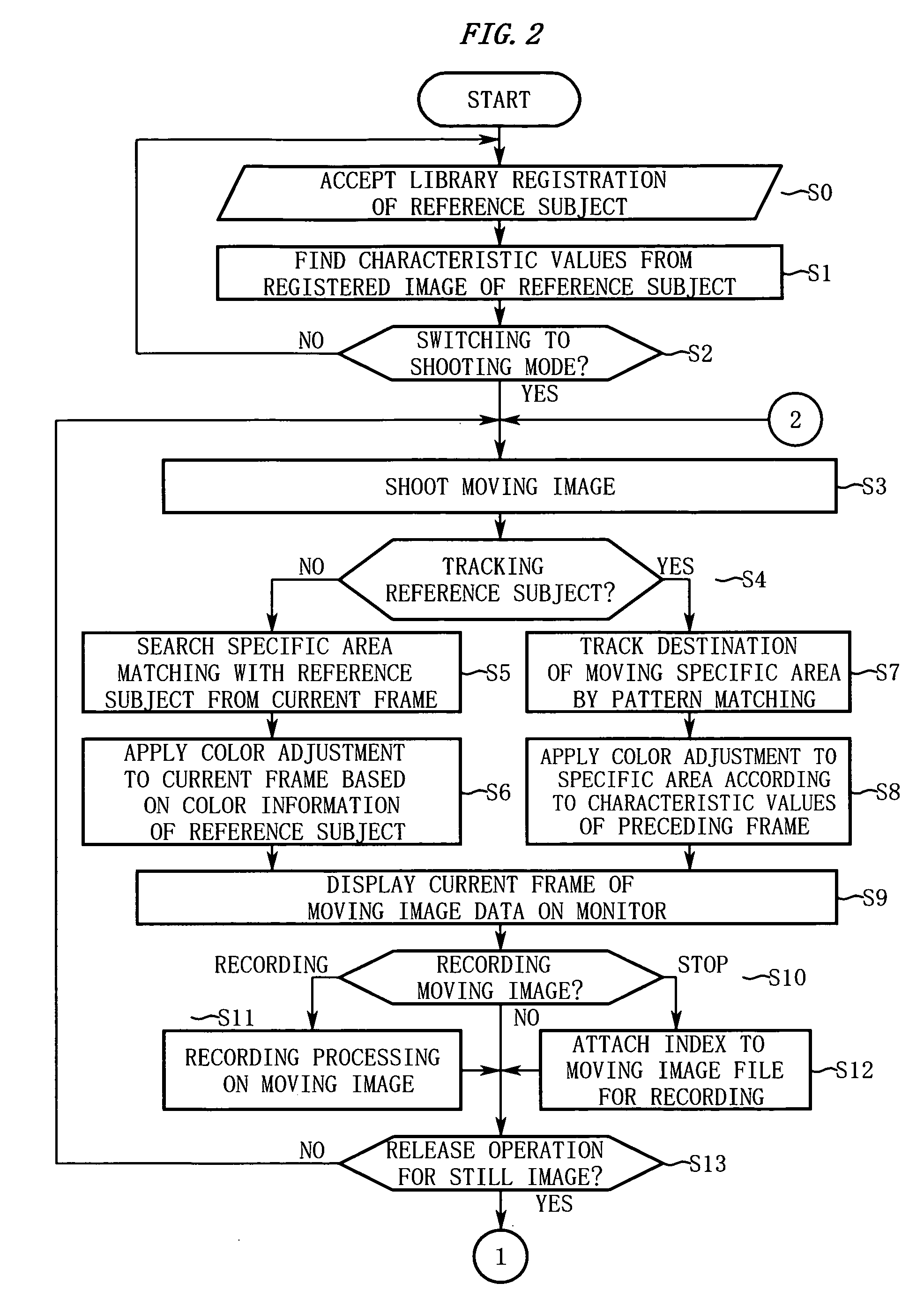
An imaging device according to the present invention includes a registration unit, an imaging unit, a searching unit, and a color adjustment unit. The registration unit registers a reference subject. The imaging unit shoots a subject and outputs image data. The searching unit searches a specific area matching with the reference subject from an image area of the image data. The color adjustment unit performs color adjustment such that color information of the specific area approximates to the color information of the registered reference subject.

Description

CROSS REFERENCE TO RELATED APPLICATION [0001] This application is based upon and claims the benefit of priority from Japanese Patent Application No. 2004-255922, filed on Sep. 2, 2004, the entire contents of which are incorporated herein by reference. BACKGROUND OF THE INVENTION [0002] 1. Field of the Invention [0003] The present invention relates to an imaging device which shoots a subject and outputs image data. [0004] 2. Description of the Related Art [0005] A conventional technique of applying color adjustment to the image data has been known. [0006] For example, Japanese Unexamined Patent Application Publication No. 2003-32699 (hereinafter, Patent Document 1), discloses the technique of setting in advance a color adjustment value for each of a plurality of representative colors and performing the color adjustment for each representative color. [0007] Moreover, Japanese Unexamined Patent Application Publication No. Hei 10-224647 (hereinafter, Patent Document 2), for example, dis...

Claims


Application Information

Patent Timeline
IPC IPC(8): H04N5/225
CPCH04N9/735H04N23/88
Inventor SUGIHARA, MARIIN, TETSUO
Owner NIKON CORP
Learn More