
Data communication method based on multi-receiver aggregation

a data communication and multi-receiver technology, applied in the field of data communication methods based on packet aggregation, can solve the problems of reducing the efficiency of transmission resources and the most significant multi-sta aggregation effect, and achieve the effect of efficient resource managemen

Active Publication Date: 2006-03-16
SAMSUNG ELECTRONICS CO LTD
View PDF5 Cites 76 Cited by
  • Summary
  • Abstract
  • Description
  • Claims
  • Application Information

AI Technical Summary

Benefits of technology

[0012] Accordingly, the present invention has been designed to solve the above and other problems occurring in the prior art. Therefore, it is an aspect of the present invention to provide a data communication method based on packet aggregation that can efficiently manage resources by determining transmission rates for reception stations (STAs) on the basis of channel state information received therefrom, aggregating packets with the same transmission rate to be transmitted to the reception STAs to form a packet group, and transmitting packet groups with different transmission rates using a single multi-rate aggregation (MRA) burst.
[0013] It is another aspect of the present invention to provide a data communication method based on packet aggregation that can minimize power consumption required for reception as one or more reception stations (STAs) initiate a reception only mode in a packet group interval including the STAs packets to be received using control information included in a multi-rate aggregation (MRA) burst.

Problems solved by technology

Therefore, the efficiency of transmission resources is reduced.
However, a multi-STA aggregation effect is, for the most part, insignificant, in the conventional HT-burst scheme.

Method used


Image

  • Data communication method based on multi-receiver aggregation
  • Data communication method based on multi-receiver aggregation
  • Data communication method based on multi-receiver aggregation

Examples


Embodiment Construction

[0025] A packet aggregation method according to an embodiment of the present invention will now be described in detail with reference to the accompanying drawings.

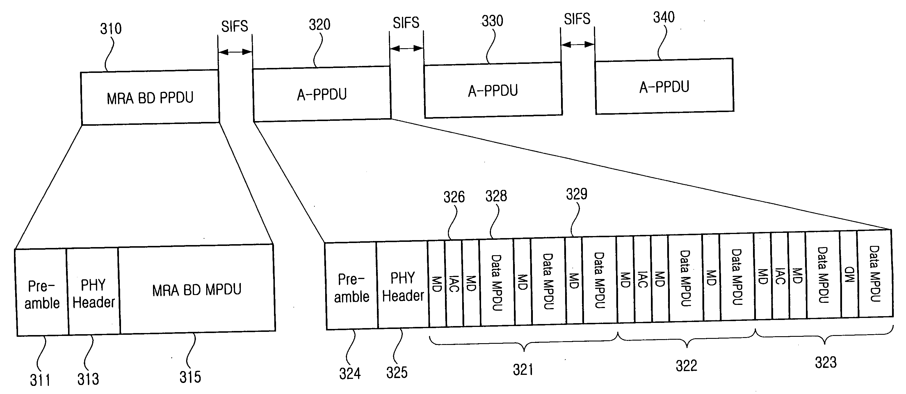
[0026]FIG. 3 is a diagram illustrating an example of a packet aggregation communication method in accordance with an embodiment of the present invention.

[0027] A multi-rate aggregation (MRA) burst in accordance with an embodiment of the present invention includes an MRA burst descriptor (BD) PHY protocol data unit (PPDU) 310 and three subsequent aggregation PPDUs (A-PPDUs) 320, 330, and 340. The MRA BD PPDU 310 is configured by a preamble 311, a PHY header 313, and an MRA BD MAC protocol data unit (MPDU) 315, and is broadcast at a basic transmission rate.

[0028] Before an MRA BD PPDU is transmitted, a transmission station (STA) groups reception STAs according to transmission rates according to a channel state of each reception STA. Then, the transmission STA aggregates packets to be sent to addresses of reception STAs be...


PUM


Abstract

A wireless communication system including transmitters for determining a transmission rate for an associated receiver according to channel state information fed back from associated receivers, and transmitting packets at the determined transmission rate. In a communication method, a transmitter groups packets to be transmitted to the receivers according to transmission rates, and generates frames configured by packets with an identical transmission rate. The transmitter aggregates frames with different transmission rates into one transmission burst, and sends the transmission burst. The data communication method based on packet aggregation can efficiently manage resources by determining transmission rates for reception stations (STAs) on the basis of feedback channel state information in a transmission STA, aggregating packets to be transmitted to the reception STAs to form a packet group, and transmitting packet groups with different transmission rates using one multi-rate aggregation (MRA) burst.

Description

PRIORITY [0001] This application claims priority under 35 U.S.C. §119 to an application entitled “Data Communication Method Based on Multi-Receiver Aggregation” filed in the United States Patent and Trademark Office on Sep. 10, 2004 and assigned Ser. No. 60 / 609,150, and to an application entitled “Data Communication Method Based On Multi-Receiver Aggregation” filed in the Korean Intellectual Property Office on Jan. 4, 2005 and assigned Ser. No. 2005-576, the contents of both of which are incorporated herein by reference.BACKGROUND OF THE INVENTION [0002] 1. Field of the Invention [0003] The present invention relates to wireless communication systems, and more particularly relates to a data communication method based on packet aggregation that can improve transmission efficiency and minimize power loss in a wireless communication system based on multiple carriers. [0004] 2. Description of the Related Art Conventional communication systems use a hierarchical frame structure to efficie...

Claims


Application Information

Patent Timeline
Patent Type & Authority Applications(United States)
IPC IPC(8): H04J3/00
CPCH04L47/10H04W28/04H04W28/18
Inventor JANG, KYUNG-HUNPARK, JONG-AELEE, DONG-JUNCHANG, JIN-BONGKIM, YOUNG-SOO
Owner SAMSUNG ELECTRONICS CO LTD
Learn More