
Communication system, server, router, and mobile communications terminal

a technology of communication system and mobile terminal, which is applied in the direction of data switching by path configuration, wireless network protocol, wireless commuication services, etc., can solve the problems of large packet loss accompanying the movement of mobile terminal, inability to update (position registration) of home agents, and difficulty in shortening the handover time, so as to achieve the effect of preventing packet loss after movement and simplifying the administrative process

Inactive Publication Date: 2006-03-16
HITACHI LTD
View PDF3 Cites 39 Cited by
  • Summary
  • Abstract
  • Description
  • Claims
  • Application Information

AI Technical Summary

Benefits of technology

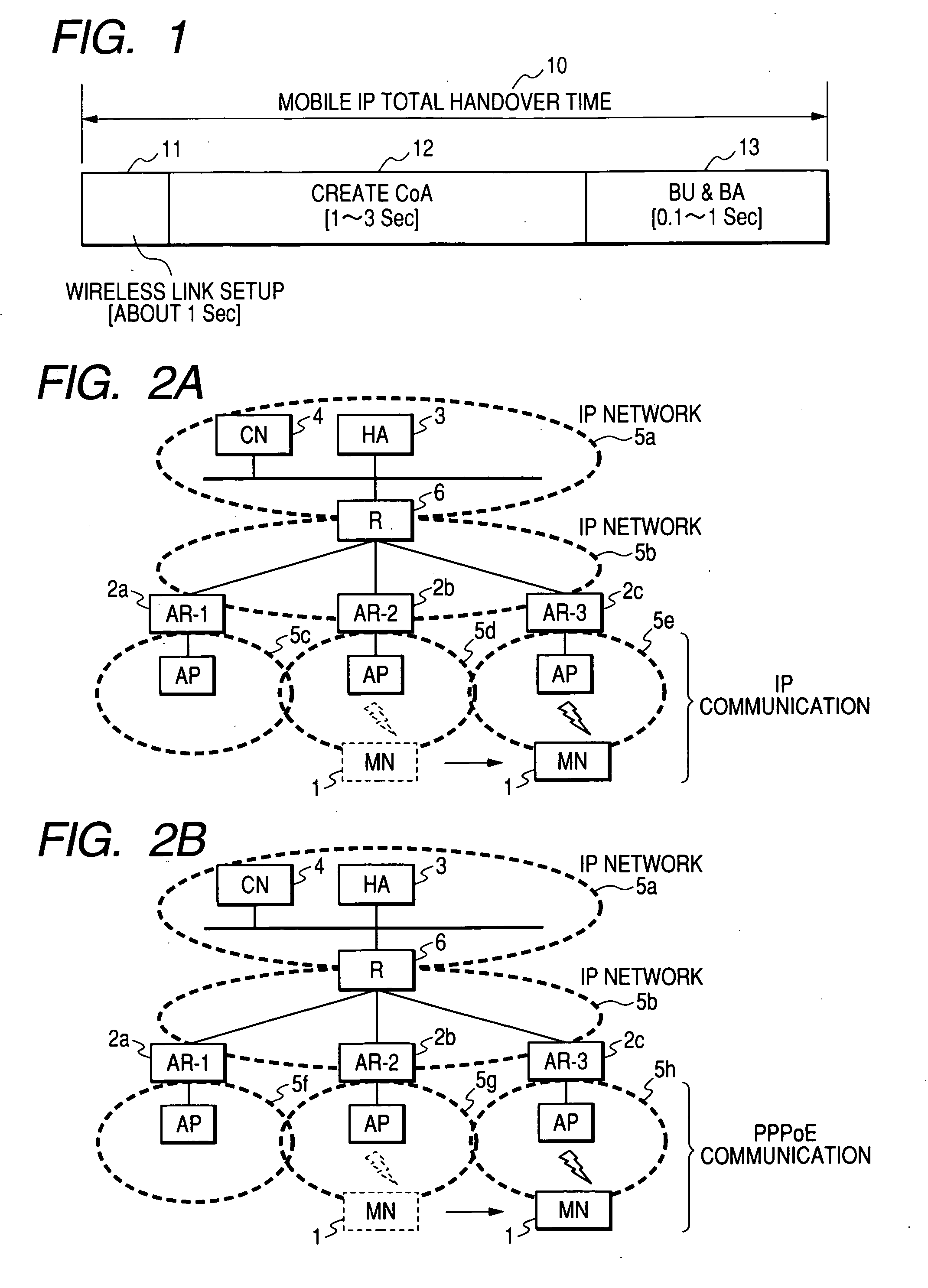
[0010] Problems that occur during handovers in the technology of the related art are described next. As shown in FIG. 1, the time 10 required for completing a handover in Mobile IPv6 is broadly grouped into a CoA generation time 12 for generating a CoA after receiving an RA with the wireless link setup 11; and a binding update time 13 up to completion of the binding update (position registration). Shortening this CoA generation time 12 and the binding update time 13 is an effective way to make the handover more efficient.
[0013] The mobile terminal of the present invention is capable of acquiring network information on the movement destination prior to movement. The invention therefore has the merit that packet loss after movement is prevented since the binding update (position registration) can be made beforehand. The invention has the further merit that management such as of settings that accompanies adding or removing access routers by the administrator can be simplified since the access router automatically collects information on nearby access routers.

Problems solved by technology

Also a binding update (position registration) of the home agent cannot be performed and shortening the handover time becomes difficult.
The technology of the related art has the further problem of large packet loss accompanying movement of the mobile terminal.

Method used


Image

  • Communication system, server, router, and mobile communications terminal
  • Communication system, server, router, and mobile communications terminal
  • Communication system, server, router, and mobile communications terminal

Examples


first embodiment

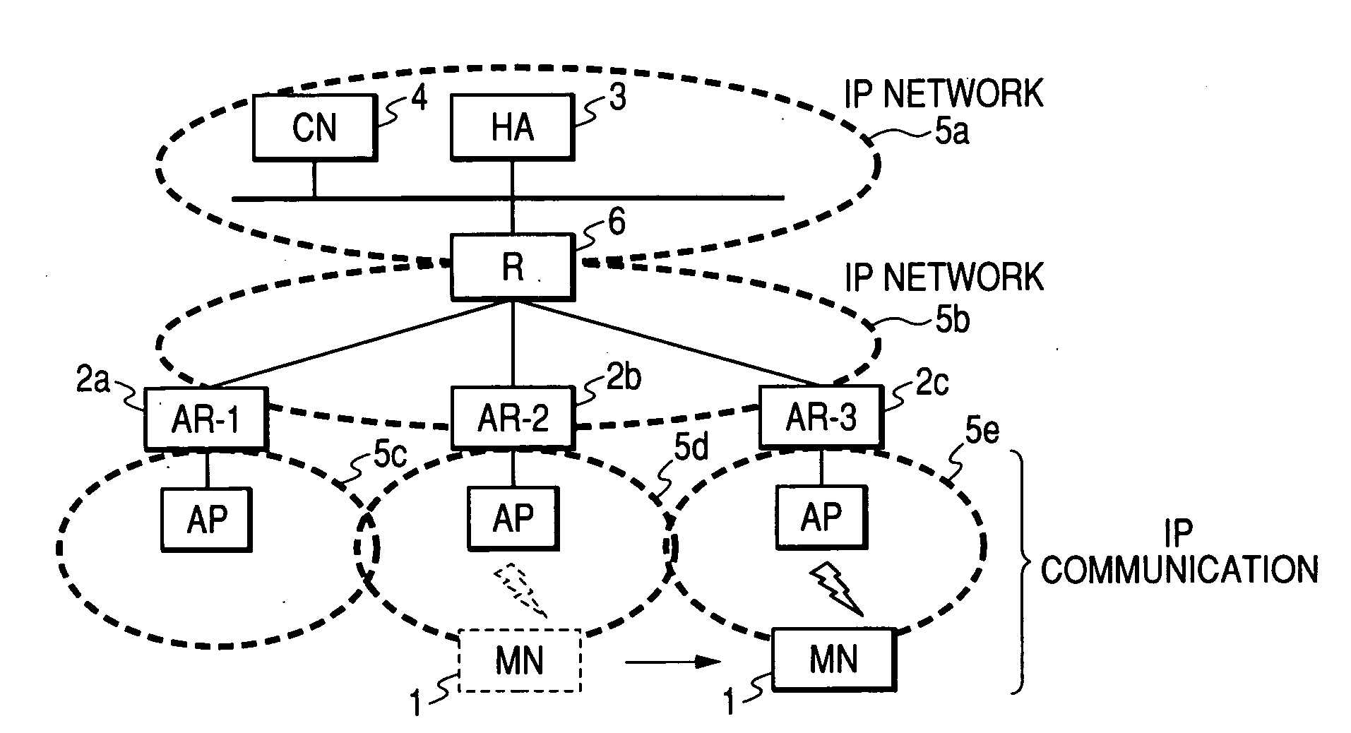
[0042] Networks connecting to each device are all comprised of IP networks as shown in the network structure of the first embodiment in FIG. 2-A. An HA (home agent) 3 for relaying the packet addressed to MN1, and a CN4 as the correspondent node (other communication party) for MN1 are connected to the home network 5a of MN1. A packet relay network 5b is installed between the home network 5a and the wireless networks (host network 5c, 5d, 5e) connected to movement destination MN1. A router 6 is installed at the boundary of the home network 5a and the packet relay network 5b. The access routers (2-A, 2b, 2c) are installed at the boundary of the host networks (5c, 5d, 5e) connected to the movement destination MN1 and the packet relay network 5b. The MN1 is IP-connected to the host network via the access points (hereafter called AP) connected to the AR (2-a, 2b, 2c).

[0043] In FIG. 2-B showing the network structure of the second embodiment, the devices connected to each network are the s...


PUM


Abstract

Mobile terminals have the problem of large packet loss during movement because the mobile terminal has no opportunity to detect movement and generate a new care-of address until a new router advertisement is received, and also cannot register the position in the home agent. The present invention is characterized in including a means to automatically collect network information on access router devices in the vicinity of a particular access router device, and a means to send information in the router advertisement including information on at least one or more adjacent access router devices. The mobile terminal selects an access router device to become the next movement destination, and the most essential characteristic is a means to register the position information beforehand in the home agent.

Description

CLAIM OF PRIORITY [0001] The present application claims priority from Japanese application JP 2004-263190 filed on Sep. 10, 2004, the content of which is hereby incorporated by reference into this application. FIELD OF THE INVENTION [0002] The present invention relates to a method for preventing packet loss that accompanies movement of the mobile terminal during mobile unit communications. The invention relates in particular to a mobile detection method for use when a mobile terminal is utilizing a Mobile IP protocol for mobile communications, and a router advertisement distribution method for access routers utilized to implement that mobile detection method. BACKGROUND OF THE INVENTION [0003] In recent years, many intensive studies have been made on IP (Internet Protocol) for mobile communication networks. [0004] The IETF (Internet Engineering Task Force) is proceeding with efforts to standardize Mobile IPv6 specifications. The essential elements comprising a Mobile IPv6 network ar...

Claims


Application Information

Patent Timeline
IPC IPC(8): H04Q7/24H04L12/46H04W36/00H04W36/08H04W48/00H04W80/04
CPCH04W36/08H04W80/04H04W48/17
Inventor MORISHIGE, TAKEHIROONO, GOTOMIZAWA, KENICHIRO
Owner HITACHI LTD
Learn More