
Spacer

a spacer and space technology, applied in the field of spacers, can solve the problems of corrugation form and cross section, and achieve the effect of improving thermohydraulic properties and high resistance to fretting

Inactive Publication Date: 2006-03-16
FRAMATOME GMBH
View PDF10 Cites 4 Cited by
  • Summary
  • Abstract
  • Description
  • Claims
  • Application Information

AI Technical Summary

Benefits of technology

[0006] It is accordingly an object of the invention to provide a spacer that overcomes the above-mentioned disadvantages of the prior art devices of this general type, which simultaneously exhibits improved thermohydraulic properties in conjunction with a high level of resistance to fretting.
[0008] Such a spacer for a fuel assembly of a nuclear reactor cooled by light water is constructed from a multiplicity of crisscrossing webs that form a grid and respectively are formed of interconnected first and second sheet-metal strips. The sheet-metal strips have corrugations in such a way that in each case neighboring corrugations form a flow sub-channel and are fashioned in such a way that they impart to the cooling water emerging from the flow sub-channel a flow component perpendicular to a vertical middle plane running between the sheet-metal strips. An improved lateral mixing of the cooling water is rendered possible thereby.
[0010] In a further advantageous refinement of the invention, the first and the second sheet-metal strips in each case have first and second corrugations that are alternately disposed in the longitudinal direction of the first and second sheet-metal strips. The first and second sheet-metal strips are assembled to form the web in such a way that each flow sub-channel is formed by a first and second corrugation. Such a sheet-metal strip and the spacer formed by it are easy to fabricate.
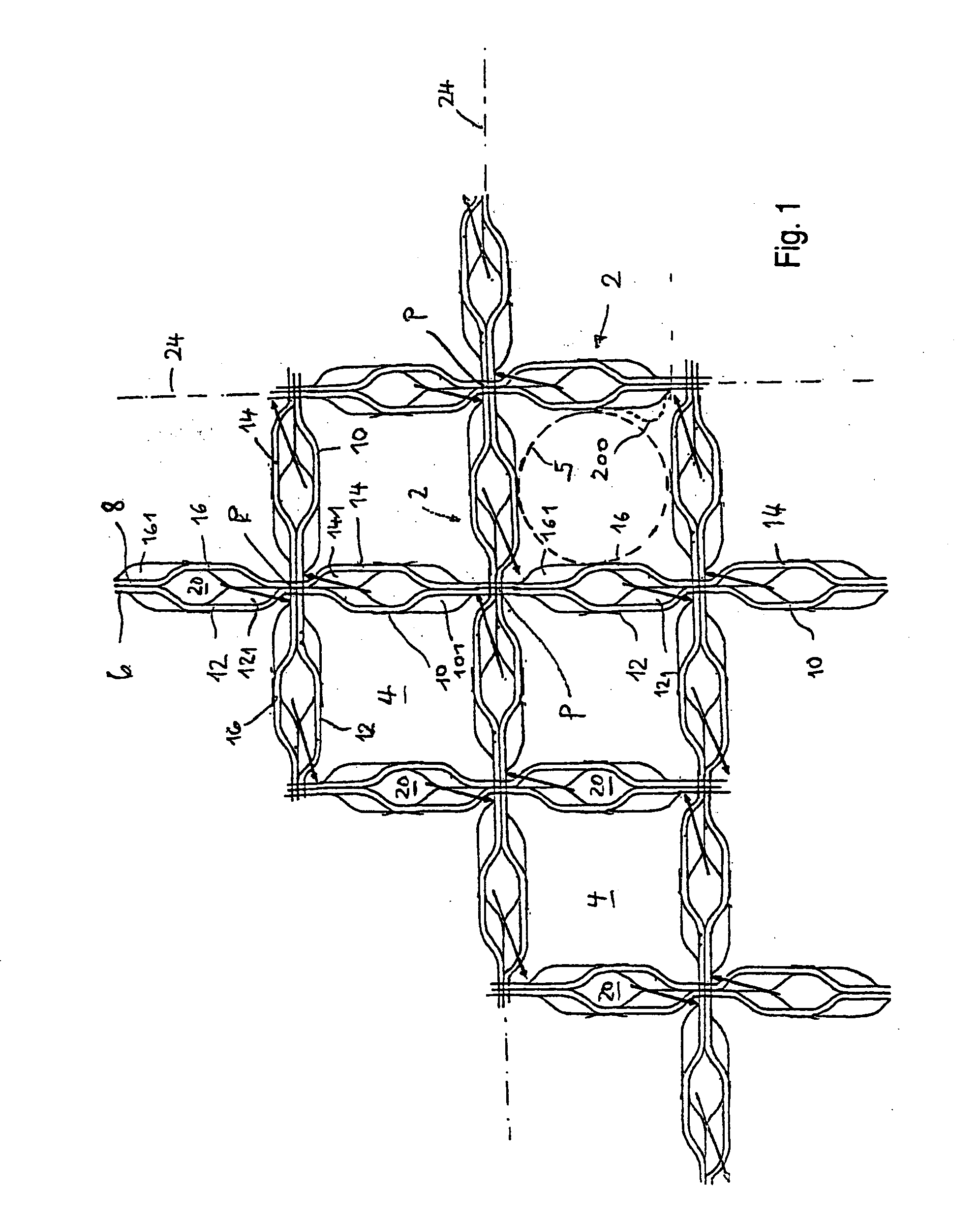
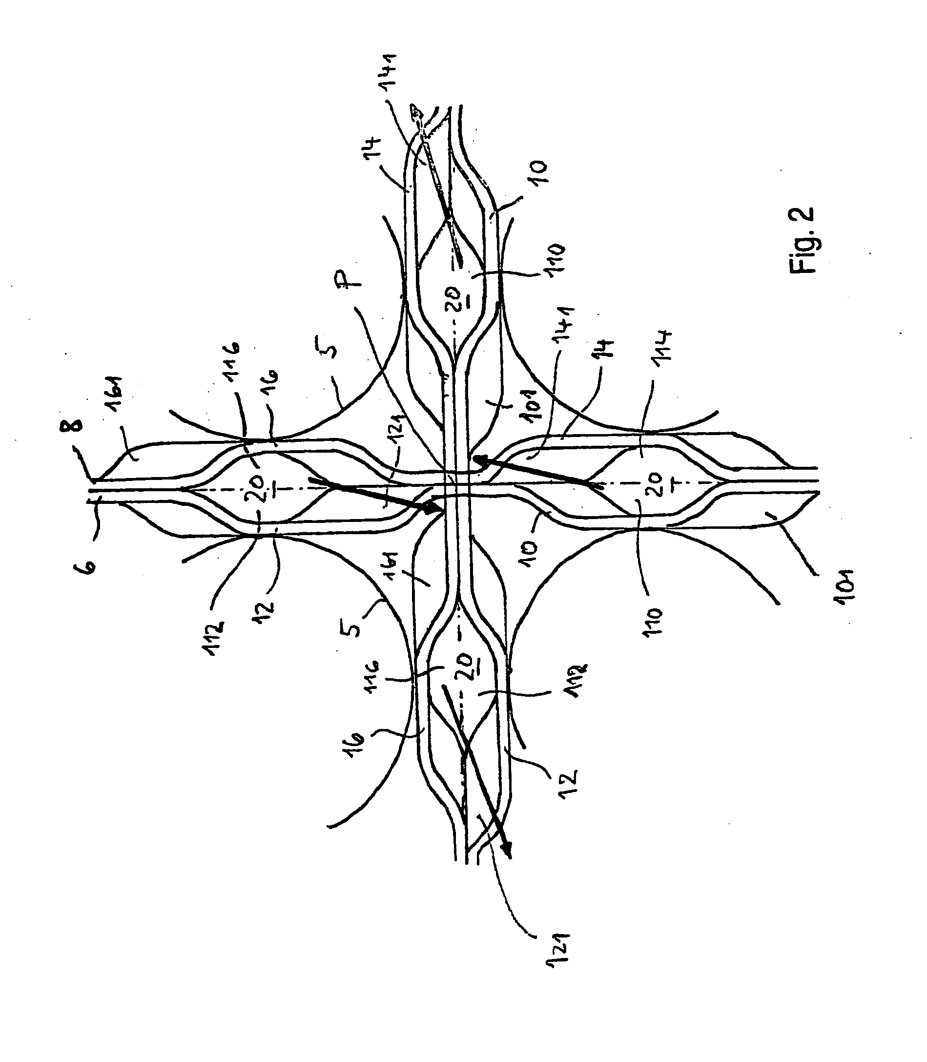
[0012] In a further preferred embodiment, the cooling water, respectively emerging from the flow sub-channel of a web, which are mutually neighboring and inclined to a crossing point of two webs, has mutually opposed flow components perpendicular to the middle plane such that a swirl flow is produced around the crossing point, in which case, in particular, the swirl flows around mutually neighboring crossing points are respectively directed in an opposed fashion along a web. This prevents the occurrence of an overall torque produced by the swirl flows and acting on the entire fuel element.

Problems solved by technology

However, forms of corrugation in which a middle region of constant cross section is present are also known.

Method used


Image

  • Spacer
  • Spacer
  • Spacer

Examples


Embodiment Construction

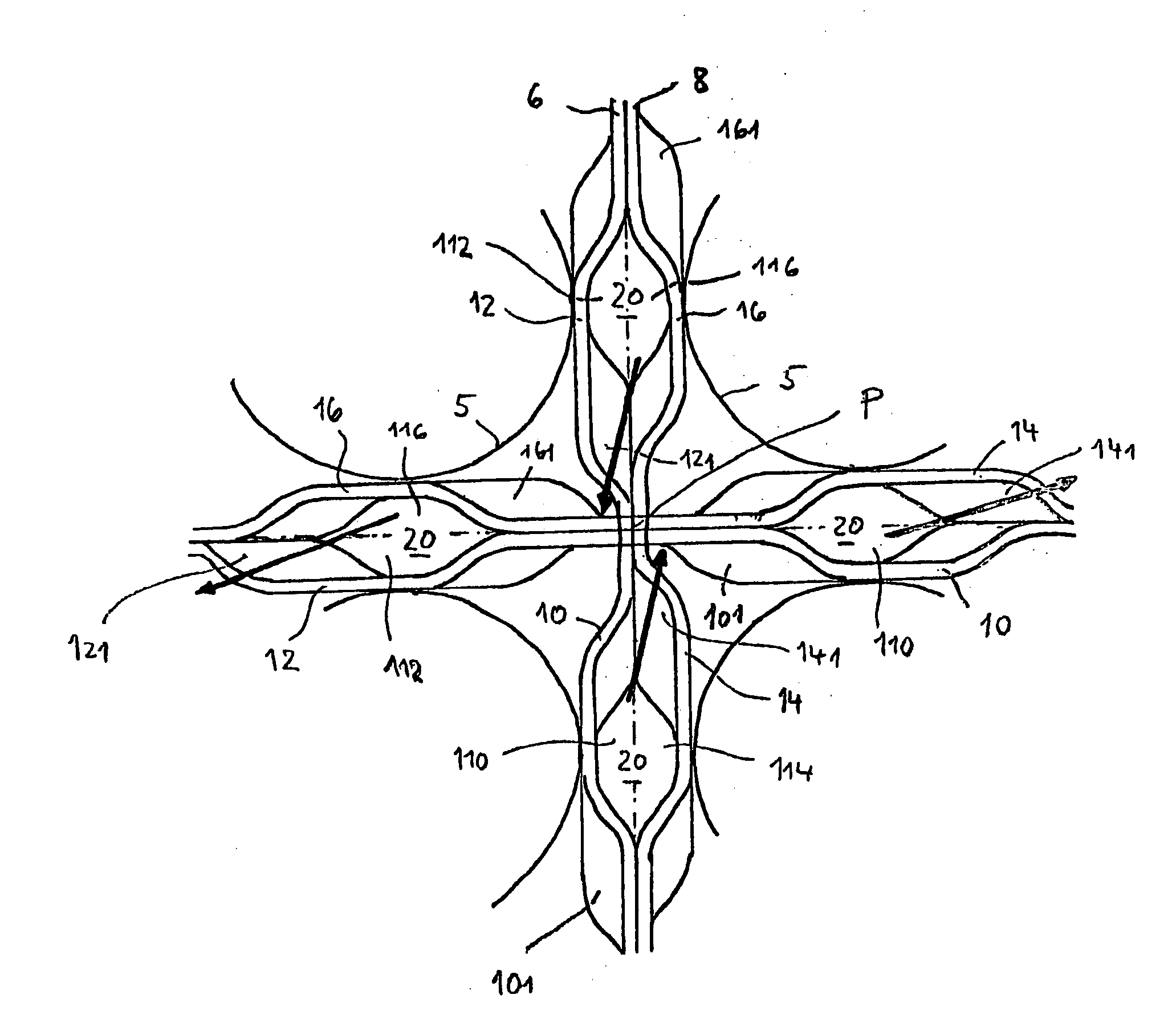
[0021] Referring now to the figures of the drawing in detail and first, particularly, to FIGS. 1 and 2 thereof, there is shown a spacer that is constructed from a multiplicity of crisscrossing webs 2 that form a grid with polygonal meshes 4, square ones in the exemplary embodiment, through which fuel rods 5 are guided. Each web 2 is assembled from a first and second sheet-metal strip 6 and 8, respectively, that are welded to one another at their mutually touching upper and lower longitudinal edges.

[0022] The first and second sheet-metal strips 6 and 8, respectively, are provided in each case with corrugations 10, 12 and 14, 16, respectively, that extend in each case into an interior of the mesh 4 respectively bounded by the sheet-metal strips 6 and 8. The corrugations 10, 12, 14, 16 serve simultaneously as bearings for the fuel rods 5 penetrating the meshes 4. In this way, there is formed between the corrugations 10, 14 and 12, 16 of the first and second sheet-metal strips 6, 8 res...


PUM


Abstract

A spacer for a fuel assembly for a light water nuclear reactor contains a plurality of intercrossed segments, which form a grid. The segments are formed from first and second metal strips which are assembled and provided with protruding parts or corrugations in such a way that the adjacent protruding parts are embodied in such a way that a flow component perpendicular to a vertical central plane which extends between the metal strips is applied to cold water running out from the flow sub-channel.

Description

CROSS-REFERENCE TO RELATED APPLICATION [0001] This is a continuing application, under 35 U.S.C. § 120, of copending international application No. PCT / EP2004 / 001515, filed Feb. 18, 2004, which designated the United States; this application also claims the priority, under 35 U.S.C. § 119, of German patent application No. 103 09 742.2, filed Mar. 6, 2003; the prior applications are herewith incorporated by reference in their entirety. BACKGROUND OF THE INVENTION [0002] 1. Field of the Invention [0003] The invention relates to a spacer for a fuel assembly of a nuclear reactor cooled by light water, as is disclosed, for example, in published European patent application EP 0 237 064 A2 (corresponding to U.S. Pat. No. 4,726,926). [0004] The known spacer is constructed from a multiplicity of crisscrossing webs that form a grid with a multiplicity of meshes. Each web is formed by two thin sheet-metal strips welded to one another. The sheet-metal strips are provided in each case with raised c...

Claims


Application Information

Patent Timeline
Patent Type & Authority Applications(United States)
IPC IPC(8): G21C3/34G21CG21C3/322G21C3/33G21C3/332G21C3/352G21C3/356
CPCG21C3/322G21C3/356Y02E30/38G21Y2002/304G21Y2004/302G21Y2002/201Y02E30/30G21C3/33G21C3/332
Inventor KEMNER, HANSBRUCH, GUNTER
Owner FRAMATOME GMBH
Learn More