

Security system
- Summary
- Abstract
- Description
- Claims
- Application Information
AI Technical Summary
Benefits of technology
Problems solved by technology
Method used
Image


Examples
Embodiment Construction
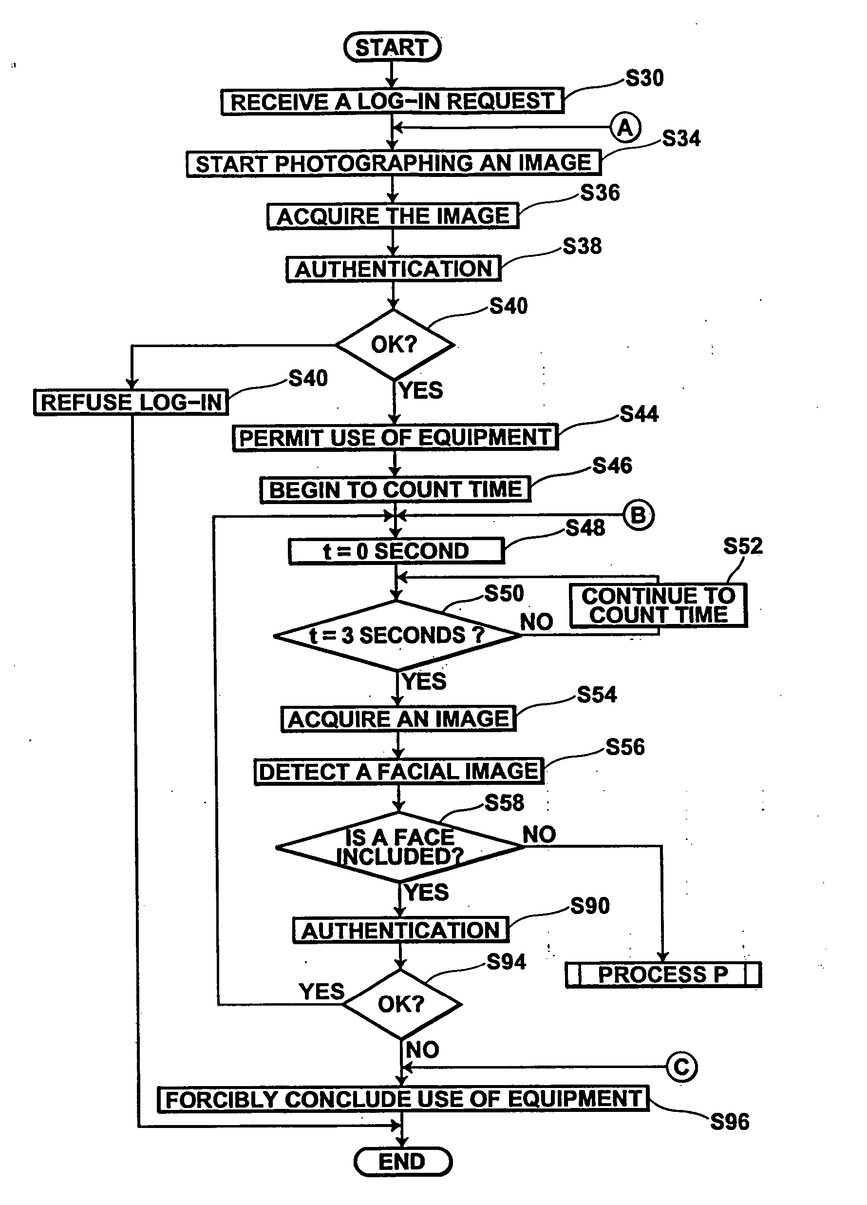
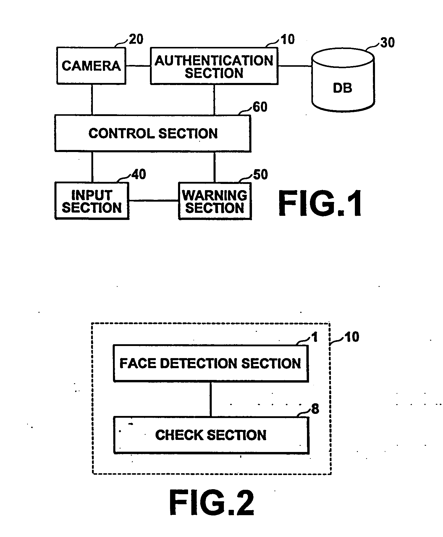
[0042]FIG. 1 shows a computer forming a preferred embodiment of a security system of the present invention. Note that for the purpose of clarity in description of the present invention, only the components relating to the security system of the present invention will be described, and descriptions and illustrations of other basic computer components will not be given. The computer of this embodiment realizes the security system of the present invention in cooperation with programs stored in an auxiliary storage, hardware (a CPU, etc.), and software (an operating system (OS), etc.).
[0043] As shown in the figure, the computer of this embodiment comprises six major components: (1) a video camera 20 for continuously photographing an image of a user present in front of the computer at the time of log-in and during use; (2) a database (DB) 30 in which a facial image of a user having qualifications to use the computer is stored; (3) an authentication section 10 for performing authenticati...
PUM
 Abstract
Description
Claims
Application Information