
Lens-fitted photographic film unit

a technology of lens fitting and photographic film, which is applied in the direction of camera body details, shutters, instruments, etc., can solve the problem that the path of the shutter blade disposed behind the taking lens cannot be sufficiently wide, and achieve the effect of increasing luminan

Inactive Publication Date: 2006-03-16
FUJIFILM HLDG CORP +1
View PDF5 Cites 5 Cited by
  • Summary
  • Abstract
  • Description
  • Claims
  • Application Information

AI Technical Summary

Benefits of technology

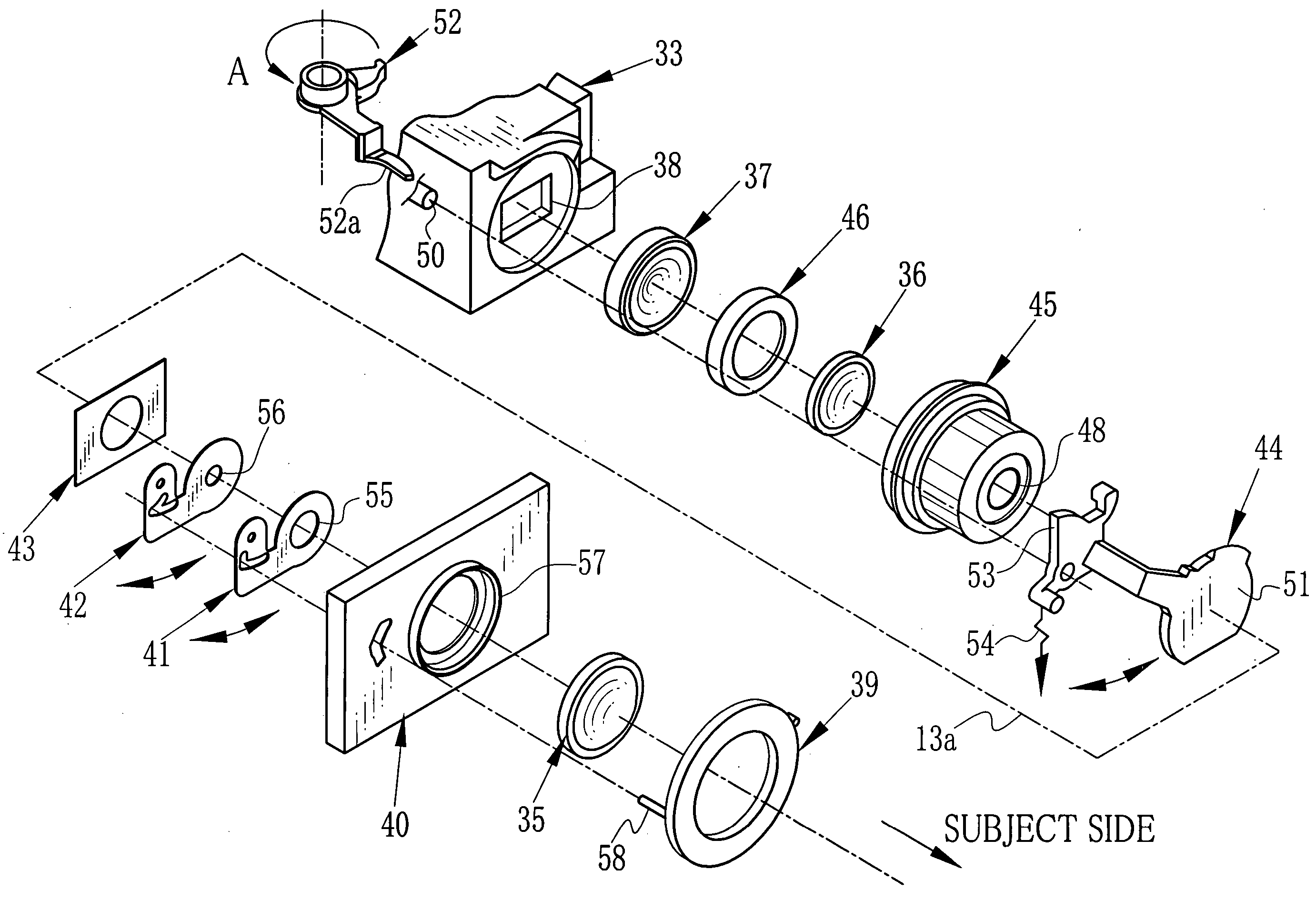
[0016] When using a convex meniscus lens as the first lens element, it is preferred to dispose a full-opened aperture and a movable stop plate between the first lens element and the second lens element, for compensation of aberration. It is also preferred to dispose the shutter blade close to the stop, that is, between the first lens element and the second lens element, for it can prevent unevenness of exposure and increase a shutter speed.
[0018] Furthermore, since the movable stop plate is disposed close to the shutter blade such as in front of or behind it, it has an effect to increase the luminance at the edge of image field.

Problems solved by technology

However, the high speed film is highly likely to cause over exposure in daylight photographing, while it has no problem in indoor photographing.
In this case, accordingly, the shutter blade disposed behind the taking lens cannot have a sufficient space for its path, since the widest portion of the periphery of the cartridge chamber interrupts the path.
However, the three lens components requires a larger space than the two lens elements and, as a result, the lens element at the rearmost is disposed so close to the focal-plane that the shutter blade cannot have an enough space for its path by the same reason as it disposed behind the two lens components.

Method used


Image

  • Lens-fitted photographic film unit
  • Lens-fitted photographic film unit
  • Lens-fitted photographic film unit

Examples


Embodiment Construction

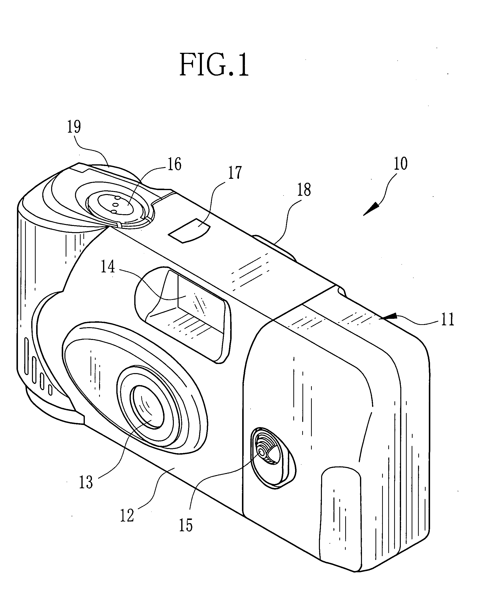
[0027] As shown in FIG. 1, a lens-fitted photographic film unit 10 of the present invention comprises a unit body 11 incorporating various photographic mechanisms therein and a label 12 adhered to around the periphery of the unit body 11. The label 12 is provided with openings for exposing various parts of the unit body 11.

[0028] The front face of the unit body 11 is provided with a taking lens 13, a front viewfinder window 14, and a stop changeover operating member 15. The top face of the unit body 11 is provided with a shutter release button 16 and a frame counter window 17, while the rear face of the unit body 11 is provided with a rear viewfinder window 18 and exposes a part of a film winding wheel 19 for winding up an exposed photo film after photo taking.

[0029] The stop changeover operating member 15 can be set in a first position, a second position or a third position, each of which selects a mode different from one another. The first position selects a small stop mode used...


PUM


Abstract

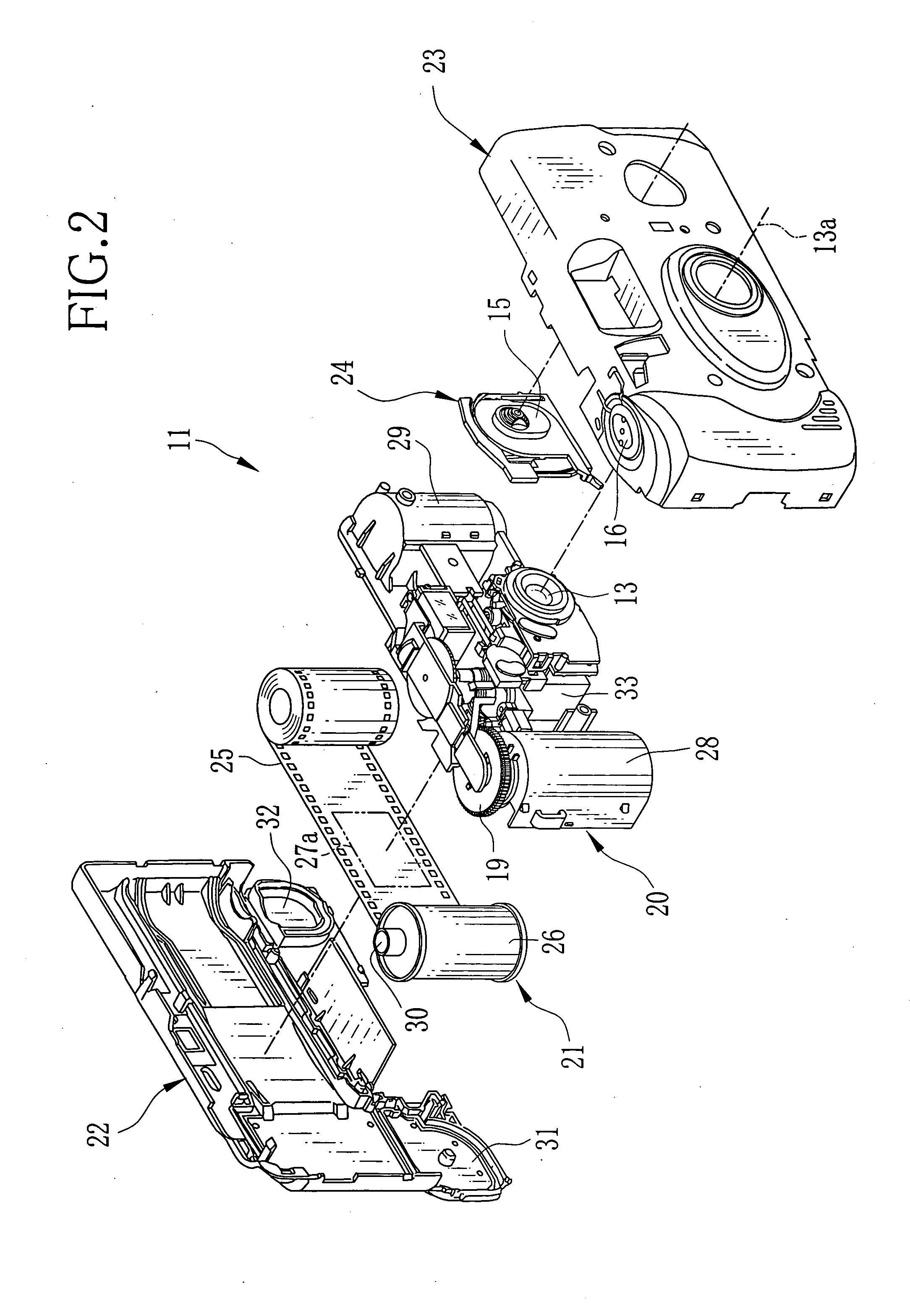
A lens-fitted photographic film unit is provided with a cassette chamber for containing a cassette and a film chamber for containing an unexposed photo film drawn from the cassette. The front portion of the cassette chamber is formed of a curved wall which cross section is in a U-shape. A taking lens has a first lens element, a second lens element, and a third lens element that are disposed from the subject side in the stated order. A shutter blade is provided with a light shield portion for opening / closing a photography light path. The light shield position is disposed between the first lens element and the second lens element, such that a part of the light shield portion enters a space formed in front of the cassette chamber when the shutter blade moves from a close position to an open position.

Description

BACKGROUND OF THE INVENTION [0001] 1. Field of the Invention [0002] The present invention relates to a lens-fitted photographic film unit having a preloaded photo film, in particular, to the lens-fitted photographic film unit having a taking lens comprising three or more lens elements. [0003] 2. Background Arts [0004] A lens-fitted photographic film unit has been provided heretofore which enable a user to easily take a picture. The lens-fitted photographic film unit has a simple structure and basically comprises a taking lens, a shutter mechanism and an unexposed photo film, while not having mechanisms for automatic focusing and automatic exposing that are normally mounted in a compact camera. [0005] The unexposed photo film is, in advance, drawn from a cartridge (a cassette) and held in a roll shape in a film chamber provided next to one side of an exposure aperture. The cartridge is loaded in a cartridge chamber (a cassette chamber) provided next to the other side of the exposure ...

Claims


Application Information

Patent Timeline
IPC IPC(8): G03B9/26
CPCG02B9/12G02B13/0035G03B2219/045G03B9/26G03B9/38G02B13/0075
Inventor KATSURA, HIROFUMICHUMAN, HIROKATSUKOIKE, KAZUMI
Owner FUJIFILM HLDG CORP
Learn More