Unlock instant, AI-driven research and patent intelligence for your innovation.

Fixed vacuum-insulated saturated steam autoclave

Inactive Publication Date: 2006-03-16
BRITISH COLUMBIA INSTITUTE OF TECHNOLOGY
View PDF15 Cites 32 Cited by
  • Summary
  • Abstract
  • Description
  • Claims
  • Application Information

AI Technical Summary

Benefits of technology

[0018] In a preferred form, the present invention provides a double-walled vacuum-sealed vessel comprising an inner cylindrical container defining a sterilization chamber therewithin, said inner cylindrical container inserted within an outer jacket wherein the mouth of the inner container is hermetically scaled to the mouth of the outer jacket under a negative pressure. The outer surface of the inner cylindrical container and the inner surface of the outer jacket define an annular space therebetween, said annular space having a permanent negative air pressure therewithin thereby providing insulation against heat transfer between the sterilization chamber and the outer jacket.

Problems solved by technology

There are certain well-known and previously described problems that occur with autoclaves.
Failure to do so could result in pockets of air remaining in the sterilizer, resulting in cold spots where articles would not be subjected to sterilizing conditions.
As well, water condensation could occur inside the chamber, also potentially entrapping microorganisms resulting in sterilization failure.
The use of a vacuum pump to evacuate air from the chamber adds additional expense and increased potential for mechanical breakdown of the autoclave.
The use of temperature and pressure sensors that are controlled by microprocessors to respond to predetermined set values also add additional expense to the autoclave.
Also, relying on preset and predetermined temperature and pressure values does not take into account variations in atmospheric pressure that exist when the autoclave is operated at altitudes other than sea level.
Another problem that occurs with autoclaves is that it becomes difficult to precisely control the temperature of the chamber, whether the technique of steam injection or steam generation within the chamber via direct application of heating elements are used.
The ability to control temperatures to + / −2 degrees in a pressurized chamber at about 270 degrees Fahrenheit (132 degrees Centigrade) is extremely difficult.
This difficulty can be due to heat loss through the chamber wall, the residual heat capacity of the sterilizers beating elements as they are intermittently turned on and off during the sterilization cycle, or due to a rapid rise in the chamber temperature after injection of steam.
However, due to the on / off application of power, and the residual heat capacity of the heating element, temperature fluctuation inside the sterilizer is generally greater than the hysteresis.
When this occurs, chamber temperature overshoots the set point, and sterilization temperatures can exceed manufacturers maximum sterilization temperature tolerances for instruments.
The main drawback of this approach is that the sterilization cycle is extended by the amount of time needed to pump down the insulating space, which can add a significant delay.
Other drawbacks of such a system are that a separate vacuum pump is required, with adds expense to the autoclave and adds the potential for mechanical breakdown.
The noise created by the vacuum pump as well as the space required for the pump and steam generator precludes a table top autoclave design.
Another drawback to the system is that it relies on the chamber warm-up coils to keep the chamber in a semi-ready state between sterilization cycles, thus expending electricity when the unit is essentially not in use.
Still another drawback to the system is that the door to the sterilizer chamber is not surrounded by a vacuum, consequently providing a large area of heat loss.

Method used


Image

  • Fixed vacuum-insulated saturated steam autoclave
  • Fixed vacuum-insulated saturated steam autoclave
  • Fixed vacuum-insulated saturated steam autoclave

Examples


Embodiment Construction

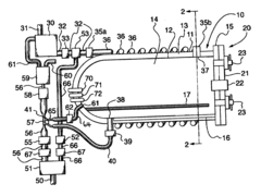
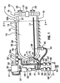
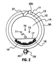
[0027] A preferred embodiment provides a portable table-top steam sterilizer comprising a sterilization chamber having a volume selected from the range of 35.4-70.8 L (i.e., 1.25-2.5 cu. ft.), the sterilization chamber being contained within a double-walled vacuum-sealed vessel having a horizontal longitudinal axis, wherein water is delivered from a self-contained water supply infrastructure, the water being heated and converted to steam in the sterilization chamber for a sterilization cycle, after which, the steam is rapidly removed by vacuum and the sterilization chamber and items placed therein are rapidly cooled and dried by a turbulent flow of air provided therethrough by concurrent application of positive and negative air pressures from a self-contained airflow piping infrastructure releasably engaged with an external supply of compressed air.

[0028] Heat-conductive metal tubing for receiving water therein is wrapped around the outer wall of the double-walled vacuum-sealed ves...


PUM


Abstract

A portable table-top steam sterilizer having a sterilization chamber contained within a double-walled vacuum-sealed vessel. Pre-heated water is delivered from a self-contained water supply infrastructure under a positive air pressure to the chamber. The pre-heated water is converted to steam within the sterilization chamber for a sterilization cycle after which, the steam is rapidly removed by vacuum and the sterilization chamber and items placed therein are rapidly cooled and dried by a turbulent flow of air. The air supply is provided by concurrent application of positive and negative air pressures from a self-contained airflow piping infrastructure releasably engaged with an external supply of compressed air. The mixtures of steam, water and air exhausted from the sterilization chamber are directed into a condenser wherein they are cooled into an air / water mixture which is transferred to an air / water separator device wherein water is separated from the air / water mixture, said water recyclable within the self-contained water supply infrastructure.

Description

CROSS-REFRFENCE TO RELATED APPLICATION [0001] This application is a continuation-in-part of our prior application Ser. No. 10 / 270,428, filed Oct. 15, 2002, currently pending.FIELD OF THE INVENTION [0002] This invention relates to steam sterilizers. More particularly, this invention relates to portable table-top steam sterilizers suitable for sterilizing therein dental or medical or veterinary instruments and supplies. BACKGROUND OF THE INVENTION [0003] Table-top steam sterilizers, commonly referred to as autoclaves, are widely used for the sterilization of instruments and other articles used in the medical, dental and veterinary disciplines. Contents of such autoclaves, when exposed to the proper conditions of temperature, time and pressure within saturated steam environments provided therein during sterilization runs, will be rendered sterile, i.e., free of any microorganisms and viruses that may have been present on the articles prior to the sterilization operation. [0004] In cont...

Claims


Application Information

Patent Timeline
IPC IPC(8): A61L2/07A61L2/24
CPCA61L2/24A61L2/07
Inventor SAWYER, MELVYN LLOYDHALSTED, NIGEL
Owner BRITISH COLUMBIA INSTITUTE OF TECHNOLOGY
Features
  • R&D
  • Intellectual Property
  • Life Sciences
  • Materials
  • Tech Scout
  • Unparalleled Data Quality
  • Higher Quality Content
  • 60% Fewer Hallucinations
Learn More