
Connecting device

a technology of connecting device and body, which is applied in the direction of coupling device connection, current collector, electrical apparatus, etc., can solve the problems of long cable, difficult storage, and the vehicle's body cannot be installed on the body part, and achieve the effect of simplifying installation and simplifying connection

Inactive Publication Date: 2006-03-16
ODU STECKVERBINDUNGSSYST
View PDF16 Cites 5 Cited by
  • Summary
  • Abstract
  • Description
  • Claims
  • Application Information

AI Technical Summary

Benefits of technology

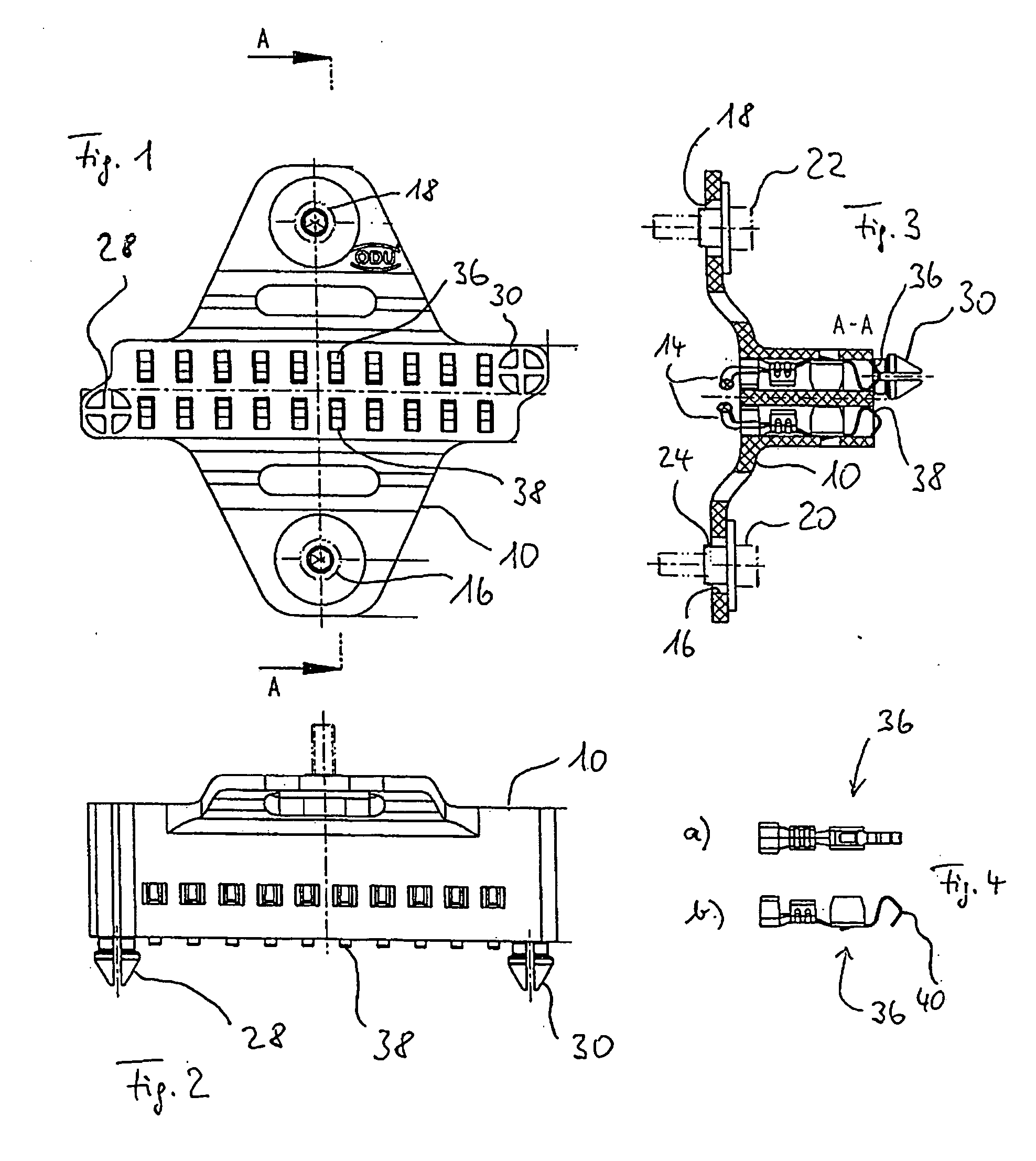
[0007] To further simplify installation and, in particular with regard to production tolerances for the trim and the two coupling devices, according to one embodiment of the invention it is particularly preferred that the first coupling device is attached to the body part in a floating manner. In other words, according to one embodiment of the invention, the first coupling device on account of its floating attachment compensates for production tolerances and minor imprecision in the attachment of the trim to the body part. The first coupling device also compensates for tolerances of fastening elements such as pins or pushbuttons, and in the attachment of these fastening elements.
[0017] The first coupling device may be formed from a single component. According to an embodiment of the invention; however, it preferably has a modular design. This results in greater flexibility in the design of the first coupling device without the need for excessive increases in inventory stock. For example, in one embodiment the first coupling device preferably has a signal module, a power module, and / or a holding module. The holding module may have an elastic design to ensure displaceability of the first coupling device in the direction of a direction of motion for coupling.

Problems solved by technology

In the above example, the trim of the vehicle cannot be installed on the body part until the plug has been inserted into the socket.
On the other hand, a long cable is problematic because it is often difficult to stow between the trim and the body part of the vehicle.

Method used


Image

  • Connecting device
  • Connecting device
  • Connecting device

Examples


Embodiment Construction

[0027] In the following detailed description, reference is made to the accompanying drawings, which form a part hereof wherein like numerals designate like parts throughout, and in which are shown, by way of illustration, specific embodiments in which the invention may be practiced. It is to be understood that other embodiments may be utilized and structural or logical changes may be made without departing from the scope of the present invention. Therefore, the following detailed description is not to be taken in a limiting sense, and the scope of the present invention is defined by the appended claims and their equivalents.

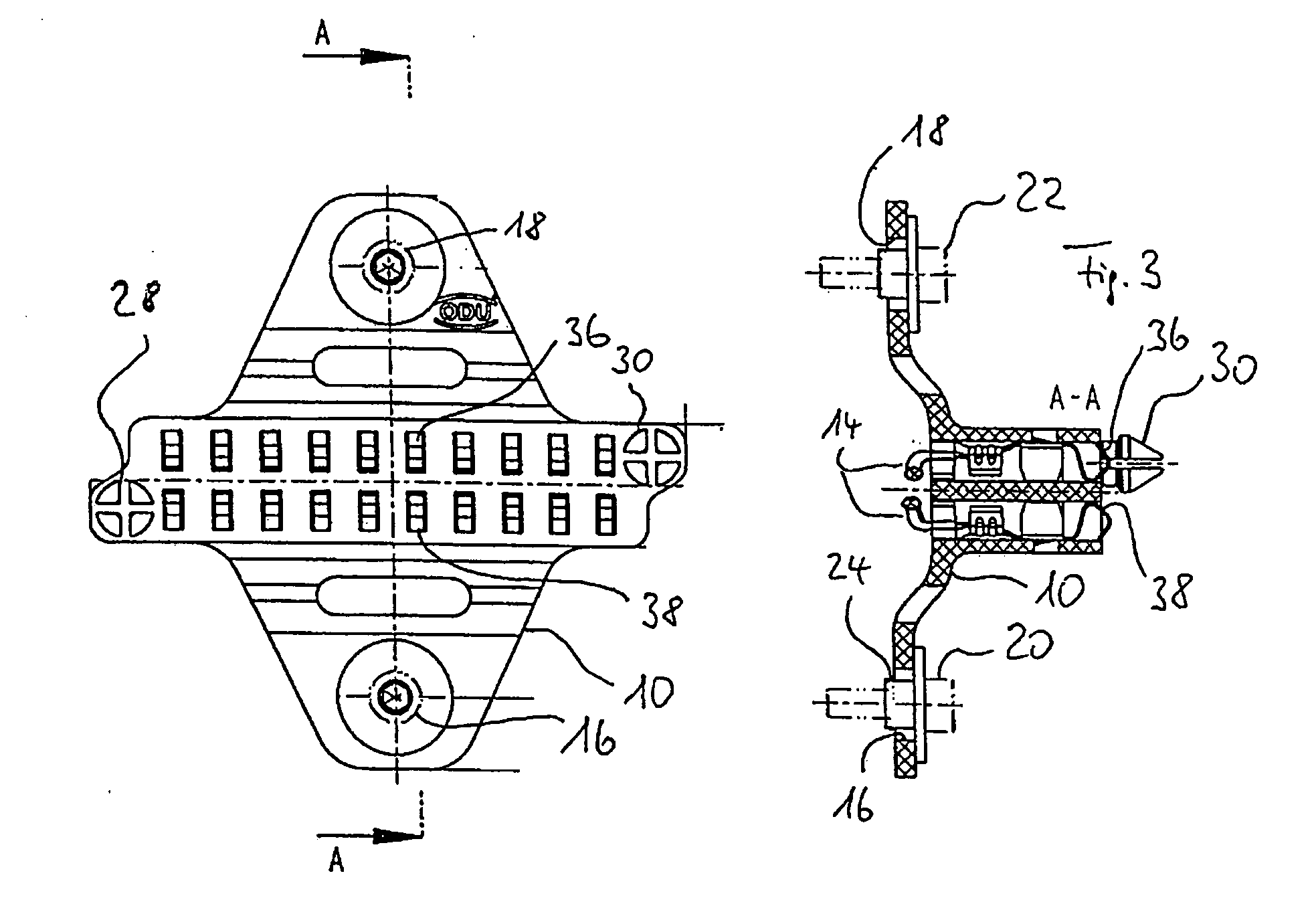
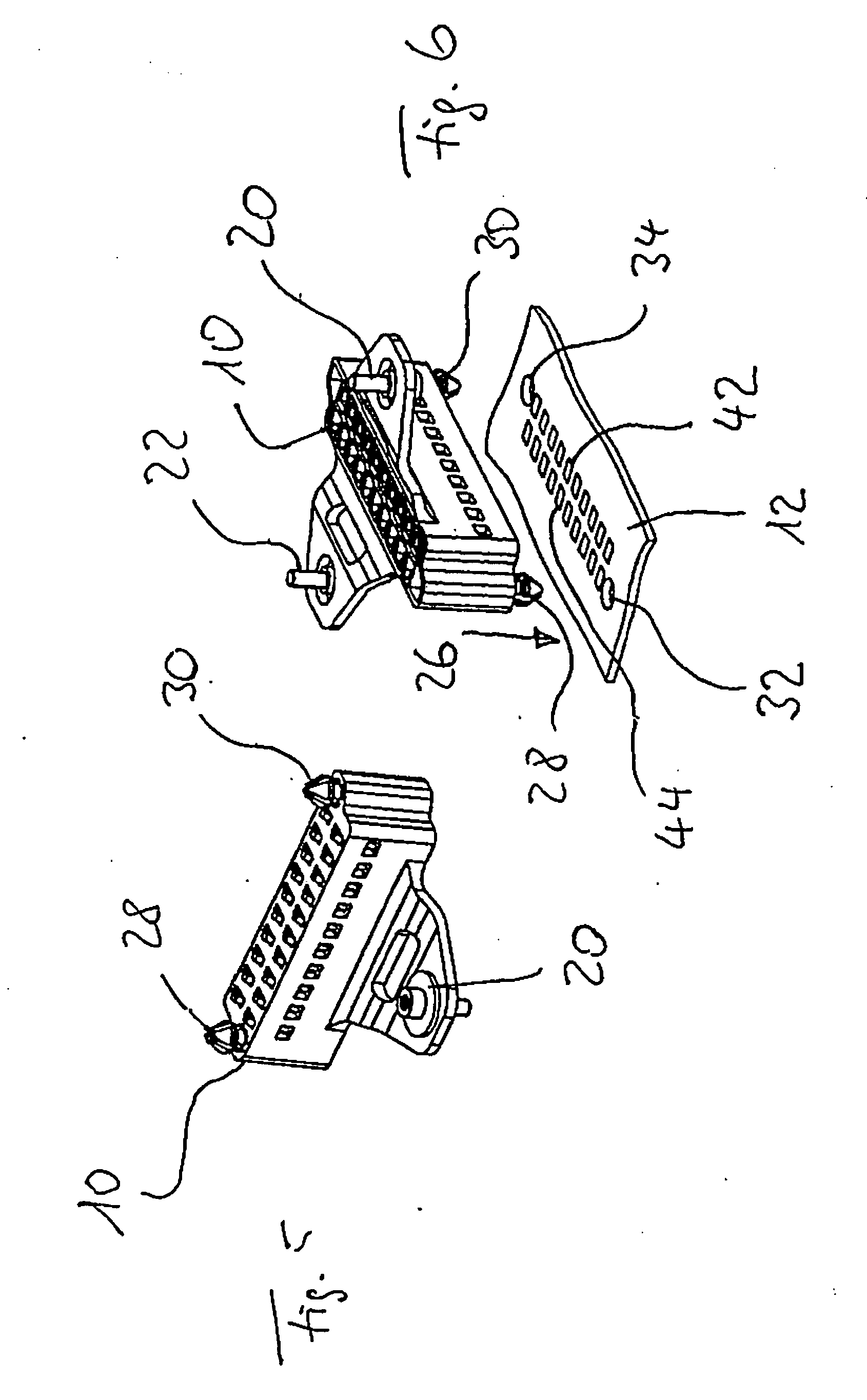
[0028] In the first exemplary embodiment of the invention illustrated in FIGS. 1 through 6, the first coupling device is provided by a plug 10. A board 12 is used as the second coupling device. The plug 10 is connected to a cable 14 which represents a first electrical connector. The cable 14 is intended to be electrically connected to wiring (not shown) for the ...


PUM


Abstract

A system and device for connecting a first electrical connector to a second electrical connector, when at least one of the two electrical connectors in the installed state is positioned between a body part of a vehicle and a trim for the body part (e.g., a roof, a door, a beam, or a floor of the vehicle). A first coupling device selectively connected to the first electrical connector. A second coupling device is selectively connected to the second electrical connector and is electrically matched to the first coupling device to form a connection of the two electrical connectors to one another.

Description

TECHNICAL FIELD [0001] The invention relates to a device for connecting a first electrical connector to a second electrical connector, where in the installed state, at least one of the two electrical connectors is situated between a body part of a vehicle (e.g., the roof, a door, a beam, or the floor of the vehicle) and a trim for the body part. More specifically, the connecting device includes a first coupling device configured to couple to the first electrical connector and a second coupling device configured to couple to the second electrical connector, the first and second coupling devices configured to provide an electrically matched connection of the two electrical connectors to one another. BACKGROUND [0002] Connecting devices of the aforementioned type are known, and generally involve plug-socket combinations. One of the two elements, the plug, for example, is attached to the end of a cable which extends along the interior of the body part of the vehicle and represents, for ...

Claims


Application Information

Patent Timeline
IPC IPC(8): H01R39/00
CPCH01R13/6315H01R12/718H01R13/73
Inventor OBERSTARR, REINHARD
Owner ODU STECKVERBINDUNGSSYST
Learn More