
System and method for on-machine probing

Inactive Publication Date: 2006-03-16
UNITED TECH CORP
View PDF9 Cites 8 Cited by
  • Summary
  • Abstract
  • Description
  • Claims
  • Application Information

AI Technical Summary

Benefits of technology

[0008] Accordingly, the system and method of this invention provides for the generation of probing instructions interwoven with machining instruction thereby eliminating tedious individual programming of probing operations.

Problems solved by technology

Difficulties arise when programming movements and operations of the probe that are to be interwoven with machining operations.
Such manual programming is tedious, complicated and time consuming.

Method used


Image

  • System and method for on-machine probing
  • System and method for on-machine probing
  • System and method for on-machine probing

Examples


Embodiment Construction

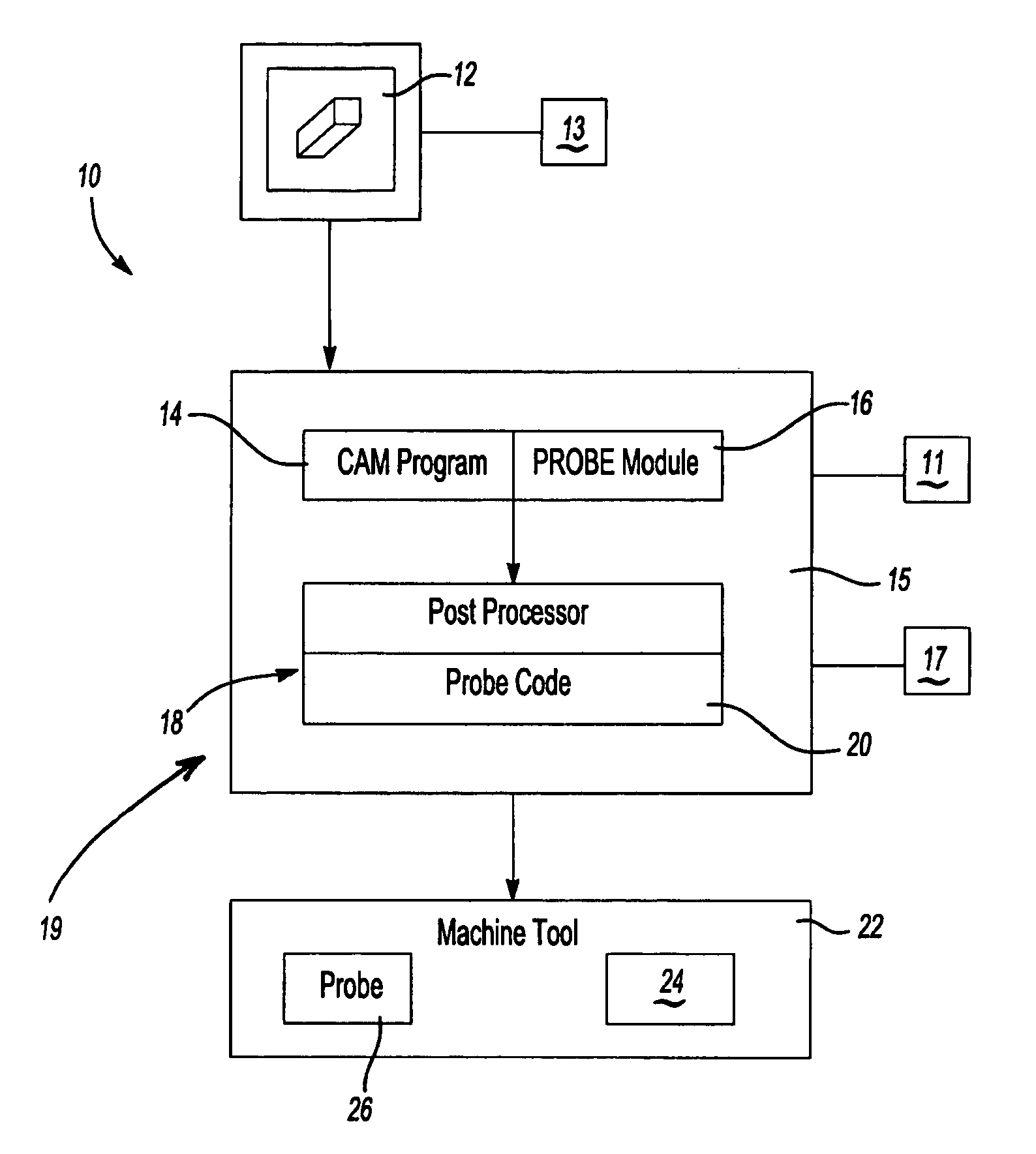
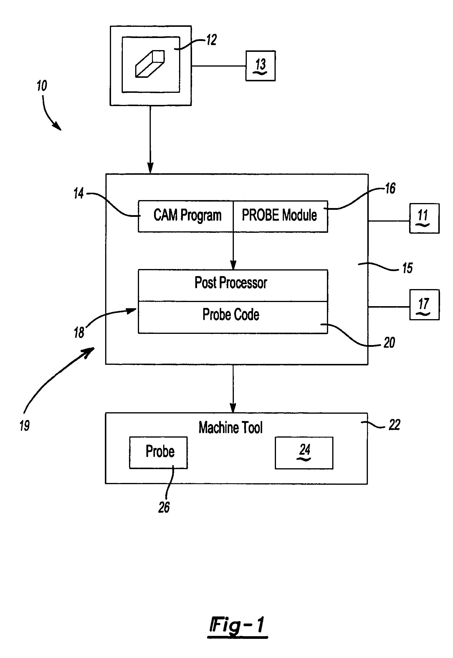
[0013] Referring to FIG. 1, a system 10 is shown schematically for generating probing operating instructions from a digital model of a part. The system 10 includes a graphical user interface 12 that displays the part geometry and a user input device 13 that provides for interaction and selection of specific features of the part produced, for example, in a CAM of Computer Aided Design (CAD) system. The graphical user interface 12 is part of a computer system 19 including a microprocessor 11, a memory device 15 and at least one computer readable storage medium 17. The computer readable storage medium 17 includes known devices, such as random access memory devices, hard disk, optical, electrical and magnetic storage devices along with other known medium.

[0014] A computer aided manufacturing program 14 that generates instructions executable on a machine tool for fabricating the part utilizes the digital model. The computer aided manufacturing program 14 may be any of the many commercia...


PUM


Abstract

A method and system for generating instructions for probing operations executable on a machine tool includes a probe module interfaced with a computer aided manufacturing program. Features selected from a digital model are utilized to determine part features for probing. The coordinates of those features are utilized to generate instructions combined and interwoven with machining instructions for fabrication of the part. The probing instructions are then converted by a post processor into executable instructions for use in a specific machine tool.

Description

BACKGROUND OF THE INVENTION [0001] This application relates to a system and method of creating a program executable on a machine tool. More particularly, this invention relates to a system and method of creating a program for operation of an inspection probe useable on a machine tool. [0002] Computer aided manufacturing (CAM) is a term associated with many aspects of part fabrication and design. Typically, a desired part configuration is created as a digital model that can be modified and manipulated through the use of a graphical user interface. The digital model is utilized to generate instructions executed by a machine tool. Conversion of part geometries from a digital model to machine language utilized by a numerically controlled machine is performed at different levels of specificity. A first level is a generic level where the geometry of a part is converted into a numerical control program that is not specific to any one machine. The generic numerical program representing inst...

Claims


Application Information

Patent Timeline
IPC IPC(8): G06F19/00
CPCG05B2219/37441G05B19/401
Inventor JESSE, CHRISTIAN
Owner UNITED TECH CORP
Features
  • Generate Ideas
  • Intellectual Property
  • Life Sciences
  • Materials
  • Tech Scout
  • Unparalleled Data Quality
  • Higher Quality Content
  • 60% Fewer Hallucinations
Learn More