Combination frame for fixing display panel module

Inactive Publication Date: 2006-03-23
QUANTA COMPUTER INC
View PDF7 Cites 13 Cited by
  • Summary
  • Abstract
  • Description
  • Claims
  • Application Information

AI Technical Summary

Benefits of technology

[0008] It is an object of the present invention to provide a combination frame to reduce the tooling cost and increase application flexibility thereof.
[0009] It is another object of the present invention to provide a combination frame utilizing various coupling devices to fix the display panel module on the frame so as to reduce the manufacturing cost of the frame.
[0010] To accomplish the above objectives, the present invention provides a combination frame for fixing a display panel module on a display shell, and generally on a front bezel of the display shell. The combination frame includes two crossbeams, two vertical beams, adjusting members, and a plurality coupling devices. The adjusting members couple the crossbeams to the vertical beams for adjusting the exterior dimension of the combination frame, and the coupling devices can adjust the interior dimension of the combination frame for precisely coupling with the display panel module.
[0011] The coupling device can be a fixing hole, a concave fixing hole, or a fixing stud. The fixing hole can be a round fixing

Problems solved by technology

These differences result in a problem for product design and manufacturing process.
However, due to size increase of the flat panel display, the tooling cost of the frame is therefore ra

Method used


Image

  • Combination frame for fixing display panel module
  • Combination frame for fixing display panel module
  • Combination frame for fixing display panel module

Examples


Example

[0017] The following description is of the best presently contemplated mode of carrying out the present invention. This description is not to be taken in a limiting sense but is made merely for the purpose of describing the general principles of the invention. The scope of the invention should be determined by referencing the appended claims.

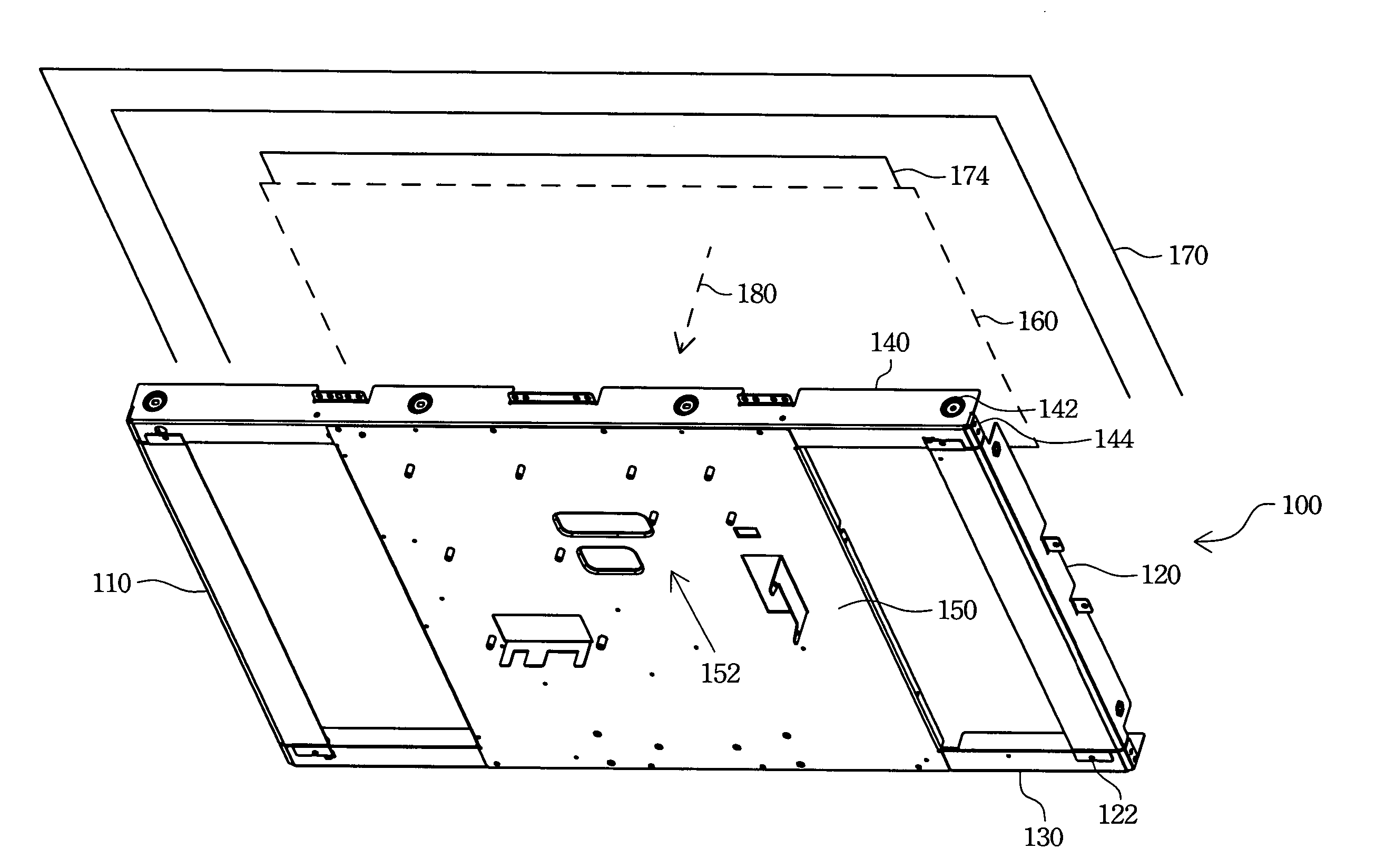
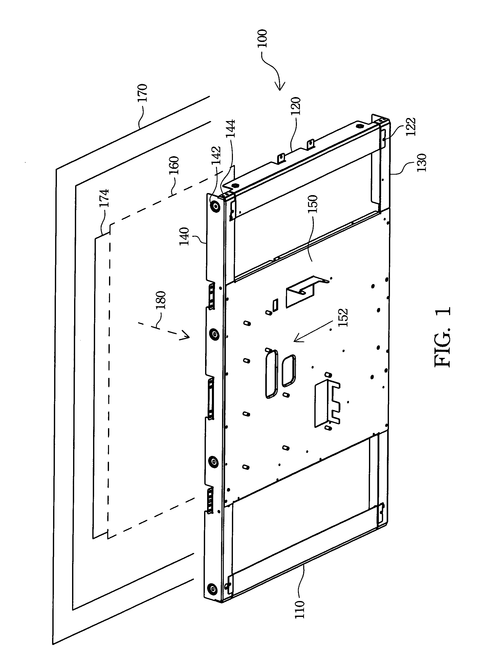
[0018]FIG. 1 is a preferred embodiment of a combination frame according to the present invention. Referring to FIG. 1, the combination frame 100 according to the present invention includes a first vertical beam 110, a second vertical beam 120, a first crossbeam 140, and a second crossbeam 130. The second crossbeam 130 further utilizes an adjusting member 122 to couple to the second vertical beam 120 so as to fine-tune vertically and / or horizontally the appearance dimensions of the combination frame 100. The adjusting member 122 can also be utilized to couple the second crossbeam 130 to the first vertical beam 110, and the first crossbeam 140 to...


PUM


Abstract

A combination frame for fixing a display panel module on a display shell is described. The combination frame is constructed by two crossbeams, two vertical beams, and a plurality of coupling devices. The coupling devices adjust an interior size of the combination frame for coupling to the display panel module exactly. The combination frame utilizes adjusting members to fine-adjust an outline size of the combination frame, and further utilizes a backboard to enhance the strength of the combination frame and fix a control circuit board of the flat panel display.

Description

RELATED APPLICATIONS [0001] The present application is based on, and claims priority from, Taiwan Application Serial Number 93128621, filed Sep. 21, 2004, the disclosure of which is hereby incorporated by reference herein in its entirety. FIELD OF THE INVENTION [0002] The present invention generally relates to a fixing frame for fixing a display panel module on a display shell. More particular, the present invention relates to a combination frame for fixing a display panel module on a display shell. BACKGROUND OF THE INVENTION [0003] Due to great progress in the electronic industry and flat panel display manufacture technology, the quality of the flat panel display is enhanced and the price thereof is reduced. The flat panel display is widely applied in both displays for personal computer and televisions for watching TV programs and enjoying the multimedia entertainment. Therefore, the quantity and the size of the flat panel displays have gradually increased in the market. [0004] A ...

Claims


Application Information

Patent Timeline
IPC IPC(8): G09F15/00
CPCH04N5/64G09F9/302
Inventor CHEN, YEN-CHUNGCHUNG, CHEN-SHENG
Owner QUANTA COMPUTER INC
Why Eureka
Try Eureka