Biasing assembly for a punching device

a technology of biasing assembly and punching device, which is applied in the field of biasing assembly, can solve the problems of shortening the punch, requiring special tools, and consuming time for disassembly of the spring assembly, and achieve the effect of facilitating the adjustment of the punch

Active Publication Date: 2006-03-23
AMADA TOOL AMERICA
View PDF25 Cites 31 Cited by
  • Summary
  • Abstract
  • Description
  • Claims
  • Application Information

AI Technical Summary

Benefits of technology

[0005] Another object of the present invention is to provide a biasing assembly for a punching device that facilitates adjustment of the punch after sharpening the punch.
[0006] Yet another object of the present invention is to provide a biasing assembly for a punching device that requires a minimal number of parts.

Problems solved by technology

Sharpening, however, shortens the punch.
Disassembly of the spring assemblies is time consuming and frequently requires the use of special tools.
Moreover, the spring assemblies of conventional punching machines include many parts that require additional labor to assemble.

Method used


Image

  • Biasing assembly for a punching device
  • Biasing assembly for a punching device
  • Biasing assembly for a punching device

Examples


Embodiment Construction

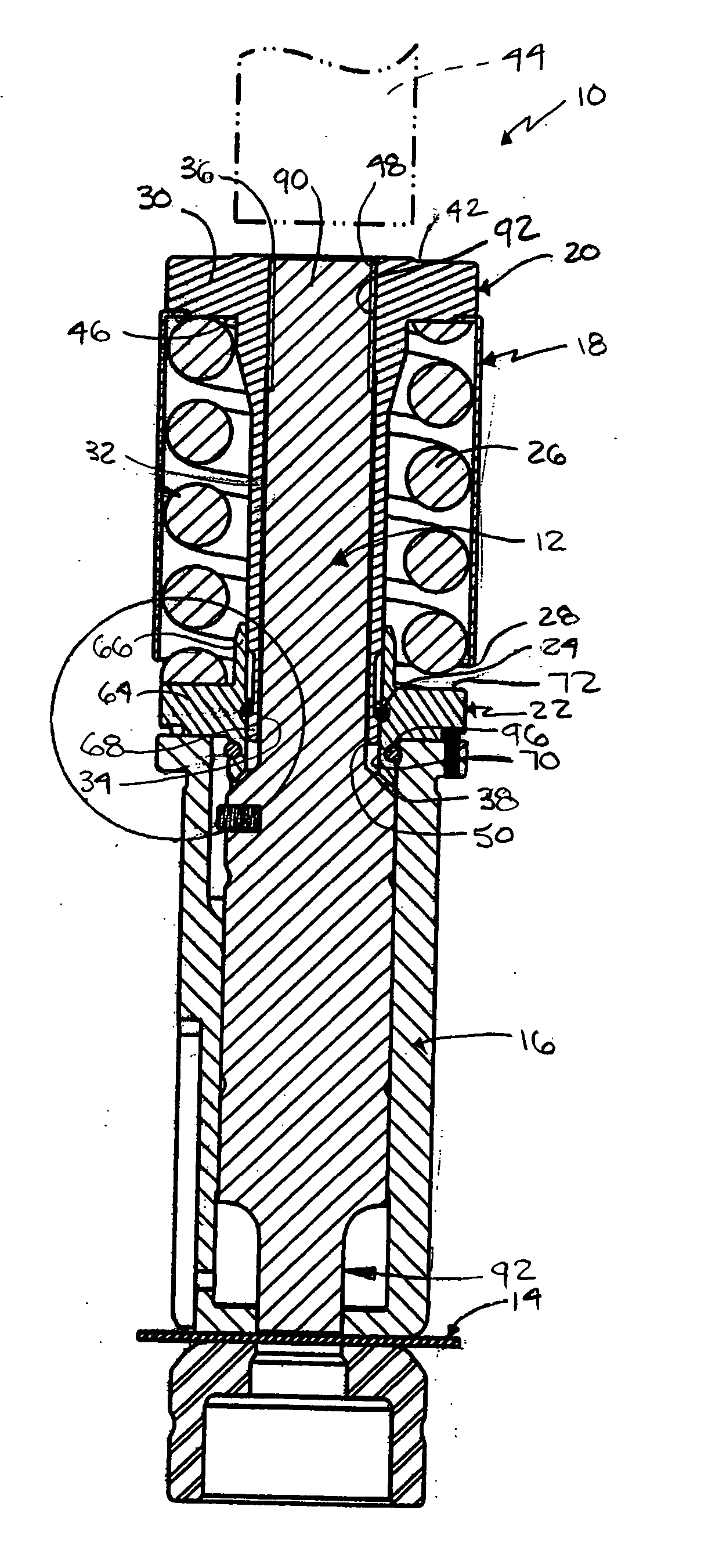
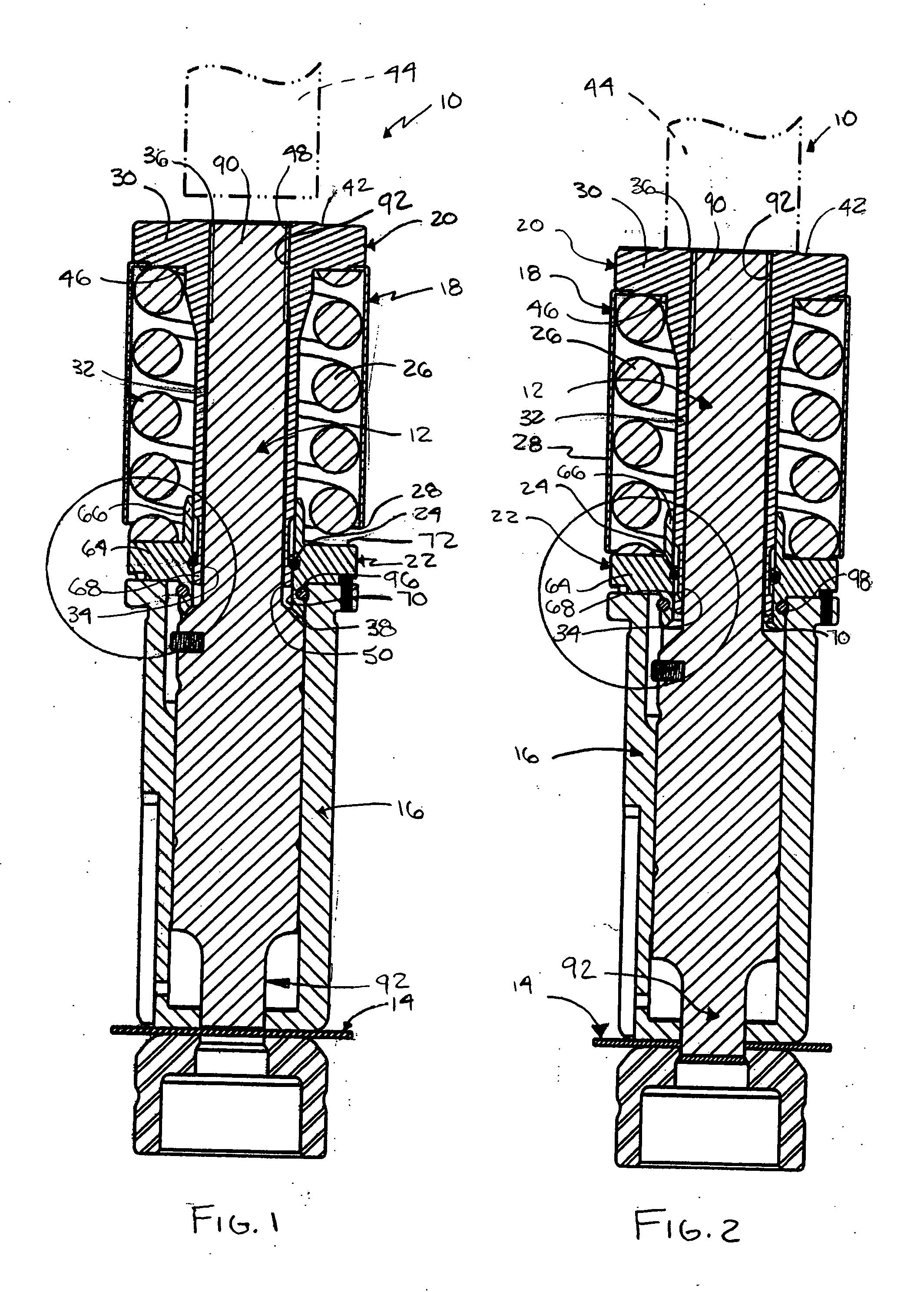
[0017] Referring to FIGS. 1-6, a punching device 10, such as turret punch press, generally includes a punch 12 for punching a work piece 14, such as sheet metal, a punch guide 16, and a biasing assembly 18 that assists in the linear movement of punch 12. Punch 12 can be removed from biasing assembly 18 and mounted back into assembly 18 without the components thereof disassembling. This allows for easy removal and adjustment of punch 12, such as when sharpening of the punch 12 is required.

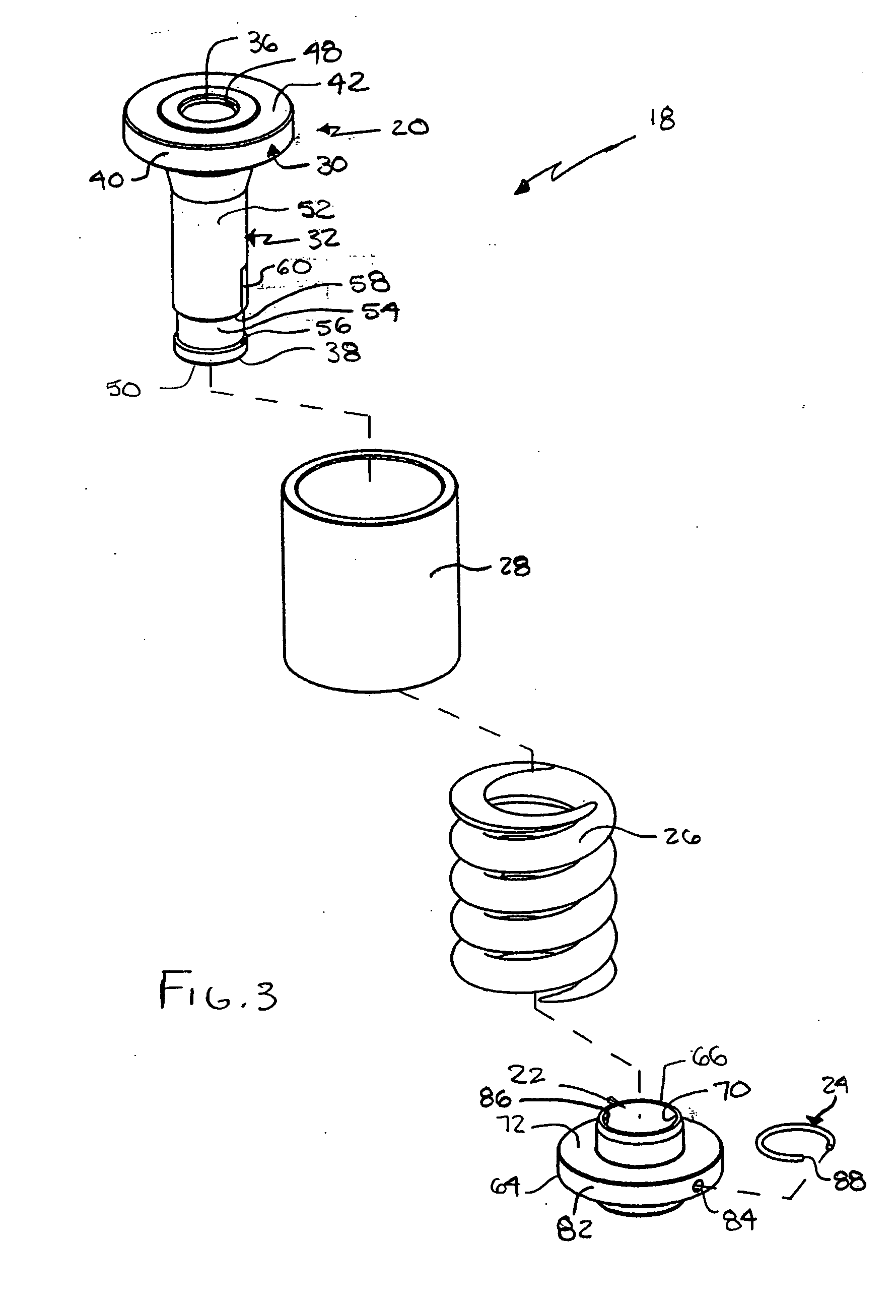
[0018] As seen in FIGS. 1-3, biasing assembly 18, in accordance with the present invention, includes minimal components. In particular, biasing assembly 18, includes a punch support member 20, a retaining member 22, a coupling member 24 coupling the punch support member 20 and the retaining member 22, and a biasing member 26 disposed between the punch support member 20 and retaining member 22. A cover sleeve 28 can be provided to cover biasing member 26, but is not required.

[0019] Punch support me...


PUM

PropertyMeasurementUnit
outer perimeteraaaaaaaaaa
perimeteraaaaaaaaaa
timeaaaaaaaaaa

Abstract

A biasing assembly for a punching device that includes a punch support member adapted to support a punch and including a head portion and a main portion extending from the head portion. The main portion has a recessed surface. A retaining member is coupled to the punch support member with the punch support member being slidable with respect to the retaining member. A coupling member is disposed between the main portion of the punch support member and the retaining member. A portion of the coupling member engages the recessed surface. A biasing member is supported between the head portion of the punch support member and the retaining member. The punch support member is movable between at least first and second positions with respect to the coupling member.

Description

FIELD OF THE INVENTION [0001] The present invention relates to a biasing assembly for use in a punching device that facilitates adjustment of the punch and remains assembled even after removal of the punch. BACKGROUND OF THE INVENTION [0002] In conventional high speed punching machines, the cutting end of the punch after a period of use requires sharpening, typically by grinding. Sharpening, however, shortens the punch. To ensure proper positioning after sharpening, the punch must be readjusted. Often conventional punching machines require complete disassembly of their spring assemblies in order to sharpen and adjust the punch. Disassembly of the spring assemblies is time consuming and frequently requires the use of special tools. Moreover, the spring assemblies of conventional punching machines include many parts that require additional labor to assemble. [0003] Examples of conventional punching machines include U.S. Pat. No. 4,440,052 to Weisbeck; U.S. Pat. No. 4,141,264 to Weisbe...

Claims


Application Information

Patent Timeline
Patent Type & Authority Applications(United States)
IPC IPC(8): B26D7/06B26F1/14
CPCB21D28/26B26F1/02B26D7/2614B21D28/34Y10T83/2155Y10T83/2159Y10T83/2166Y10T83/8785Y10T83/8867Y10T83/9423Y10T83/9428Y10T83/9476B26F1/00B26F1/14B21D28/346B21D45/006
Inventor SUGIZAKI, FUMITAKAIIZUKA, HITOSHIDRIES, EDWARD A.
Owner AMADA TOOL AMERICA
Why Eureka
Try Eureka