
Screw press head detector

a detector and screw press technology, applied in the direction of measuring devices, instruments, manufacturing tools, etc., can solve the problems of belt wear, easy loss of elasticity, and inability to accurately measure the screw thread, so as to achieve simple operation, time-saving measurement, and precise results

Inactive Publication Date: 2006-03-23
WU CHUN NAN
View PDF3 Cites 7 Cited by
  • Summary
  • Abstract
  • Description
  • Claims
  • Application Information

AI Technical Summary

Benefits of technology

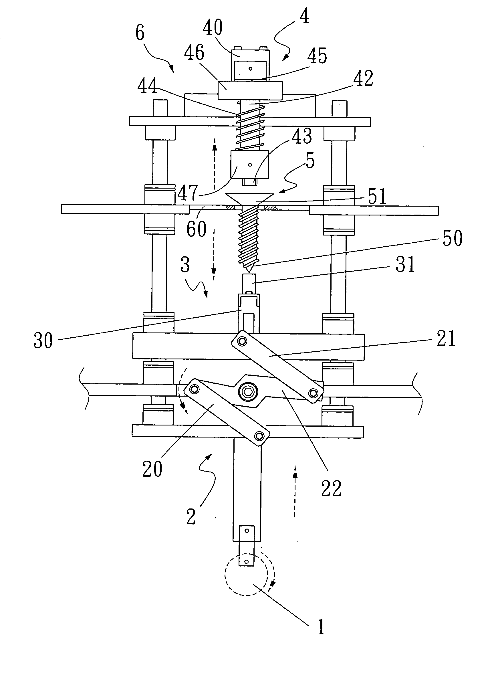
[0008] The primary objective of the present invention is to overcome the foregoing shortcoming and avoid the existing deficiency by providing a screw press head detector that can provide a precise, simple-to-operate and time-saving measurement and measure different options at the same time. The screw press head detector comprises an eccentric mechanism, an ascending / descending rod module, a fixed rod module and a probe module; wherein the upper and lower ends of the ascending / descending rod module are coupled to the eccentric mechanism and the fixed rod respectively by screws. The eccentric mechanism is pulled downward to drive the ascending / descending rod module at the top of a pulling rod of the eccentric mechanism to move downward and push another ascending / descending rod module to move upward as to press the connected fixed rod upward against the bottom of the screw, and press the probe module downward into a hole on the screw head. The testing screw head is rotated at the same angle and fixed with the hole of the screw by a groove of the probe rotary head.

Problems solved by technology

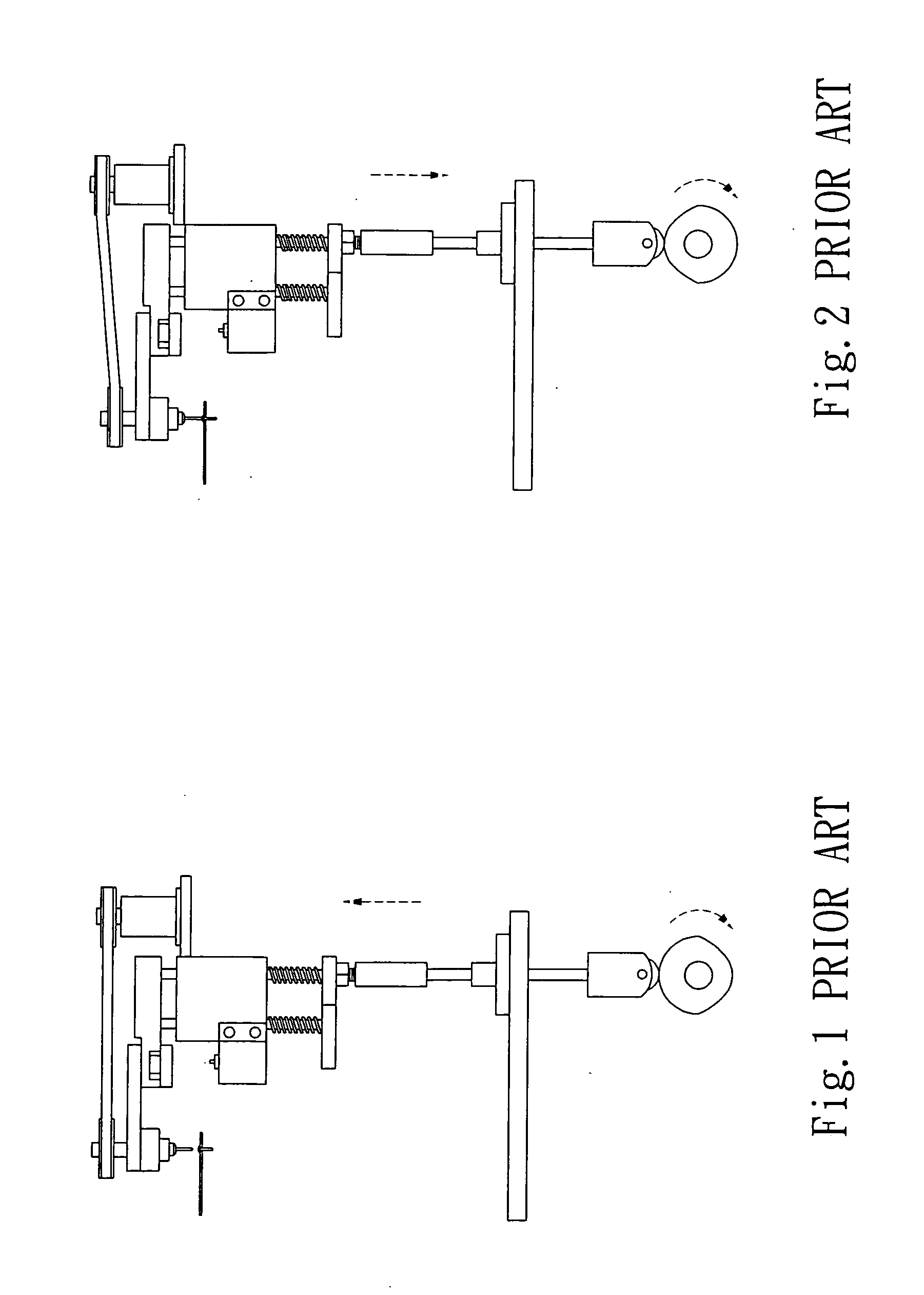
Although these screw press detectors have the functions of measuring the length, size, and thread depth required by users, they still have the following drawbacks:
When the prior-art screw press head detector detects screws, a motor is rotated to align the position of a sink hole, but the screw is under the rotation and the screw thread cannot be measured accurately and determined whether or not it meets the user's requirement.
As a result, the fixed board is worn and damage easily after its use for a long time, and causing errors and inaccuracy to the measurement.
The belt is moved reciprocally to detect the depth, but the belt will be worn and lose its elasticity easily after its use for a long time.
Therefore, the belt cannot drive the probe properly anymore, which causes errors.
When the prior-art press head detector detects the length, size and thread depth of the screw, it is necessary to go through many complicated steps and cannot complete detecting all required functions at a time.
Furthermore, the detection involves too many components and thus makes the assembly too complicated.
The prior-art screw press head detector uses the rotation of a cam to drive the detector to move vertically up and down, but the rotation of the cam produces friction which will wear out and damage the cam after its use for a long time.
As a result, the detector cannot be driven to a fixed point and gives rise to errors.
Further, indented holes may be produced by the friction of the cam after a long period of time, and thus affecting the accuracy of the detection.

Method used


Image

  • Screw press head detector
  • Screw press head detector
  • Screw press head detector

Examples


Embodiment Construction

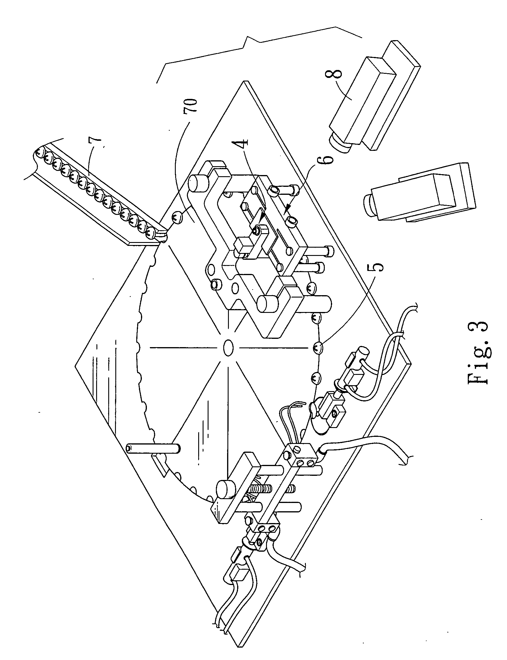
[0019] Please refer to FIGS. 3 and 4 for the screw press head detector according to the present invention. The detector comprises an eccentric mechanism 1, an ascending / descending rod module 2, a fixed rod module 3 and a probe module 4; wherein the eccentric mechanism 1 is driven to rotate a pulling rod 10 of the eccentric mechanism 1 as to pull the ascending / descending rod 20 down and push another set of ascending / descending rod 21 up, such that the fixed rod 31 is pressed upward against the bottom of a screw 50, and the probe module 4 is pressed downward into a polygonal hole 52 on the screw head 51 as shown in FIGS. 4, 5 and 9. The screw testing head 40 is rotated and fixed at the same angle with a polygonal hole 52 on the screw 5 (as shown in FIG. 9) by a groove 41 on the probe rotary head 40 (as shown in FIGS. 7 and 8).

[0020] The forgoing eccentric mechanism 1 is situated on one side of a base 60 of the screw press head detector 6 and coupled securely to the pulling rod 10 of ...


PUM


Abstract

The present invention discloses a screw press head detector, which comprises an eccentric mechanism for driving an ascending / descending rod module to press a probe module downward and using a groove of the prove rotary head to rotate and fix a screw at the same angle with the polygonal hole of the screw in order to facilitate the detection of the depth of the polygonal hole of the screw, and push the fixed rod upward to fix the screw and facilitate the measurement of the length, thread pitch, screw thread angle and thread pitch between the bottom of the screw head to the screw thread as to constitute a screw press head detector featuring the simple operation procedure, accurate measurement, capability of detection several items and time saving.

Description

FIELD OF THE INVENTION [0001] The present invention relates to a screw press head detector, more particularly to a screw press head detector having the simple operation procedure, accurate measurement, capability of detection several items and time saving features. BACKGROUND OF THE INVENTION [0002] At present, there are various types of screw press detectors (as shown in FIGS. 1 and 2) sold in the market. Although these screw press detectors have the functions of measuring the length, size, and thread depth required by users, they still have the following drawbacks: [0003] 1. When the prior-art screw press head detector detects screws, a motor is rotated to align the position of a sink hole, but the screw is under the rotation and the screw thread cannot be measured accurately and determined whether or not it meets the user's requirement. [0004] 2. Since the bottom of the screw head of the prior-art screw press head detector is in touch with a fixed board, therefore when the screw ...

Claims


Application Information

Patent Timeline
IPC IPC(8): B30B15/14
CPCG01B11/2425
Inventor WU, CHUN-NAN
Owner WU CHUN NAN
Learn More