Measuring method of transconductance parameters

A measurement and transconductance technology, which is applied in the direction of measuring devices, measuring electrical variables, electronic circuit testing, etc., can solve the problem of increasing the test cost of the inverter oscillation circuit measurement time and reduce the test cost and measurement time. Effect

Inactive Publication Date: 2012-12-19
PRINCETON TECH CORP
View PDF0 Cites 2 Cited by
  • Summary
  • Abstract
  • Description
  • Claims
  • Application Information

AI Technical Summary

Problems solved by technology

[0006] However, using the AC measurement method to measure the transconductance parameters of the inverter oscillator circuit will increase the measurement time and test cost

Method used


Image

  • Measuring method of transconductance parameters
  • Measuring method of transconductance parameters
  • Measuring method of transconductance parameters

Examples


Embodiment

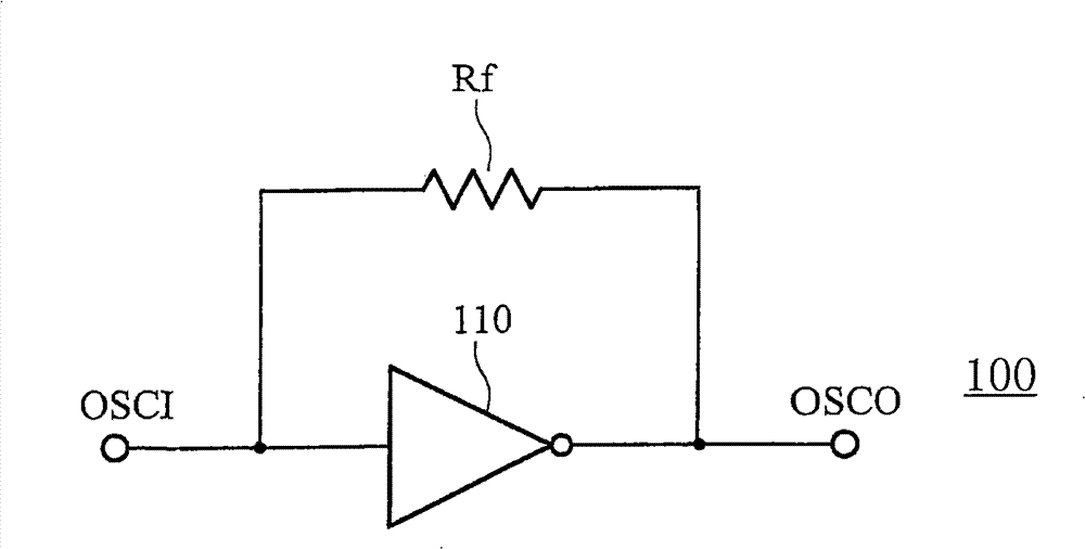
[0038] Figure 3 to Figure 6B A measuring circuit for measuring the transconductance of an inverter oscillator circuit according to an embodiment of the present invention is shown. image 3 A measuring circuit is shown for measuring the voltage value of the bias voltage in the oscillator circuit of the inverter. First, the input terminal OSCI and the output terminal OSCO are floating. Next, measure the voltage at the output terminal OSCO to obtain the bias voltage V bias . exist image 3 , due to the current I flowing through the feedback resistor Rf Rfis zero, so the voltages at the output terminal OSCO and the input terminal OSCI have the same bias voltage V bias voltage value.

[0039] Figure 4 A measurement circuit is shown for measuring the resistance value of the feedback resistor Rf in the inverter oscillation circuit. exist Figure 4 Among them, the DC voltage source 410 is coupled to the input terminal OSCI for providing the DC voltage to the inverter oscill...


PUM


Abstract

The invention relates to a measuring method of transconductance parameters, which is suitable for transconductance of a measurement oscillating circuit; wherein the oscillating circuit comprises an inverter; the measuring method of transconductance parameters comprises the following steps: connect the input end and the output end of the inverter in a floating way and measure output end to obtain bias voltage of the inverter; connect the input end in a floating way and respectively provide first voltage and second voltage for the output end, so as to measure first current corresponding the first voltage and second current corresponding to the second voltage from the output end; the first voltage and the bias voltage have the same voltage level; according to the first voltage, the second voltage, the first current and the second current, the output resistance of the inverter is obtained; according to the output resistance, the transconductance of the oscillating circuit is obtained. In the invention, the transconductance parameters of the oscillating circuit of the inverter in an integration circuit are measured by a direct-current way, the measuring time is effectively reduced and the test cost is reduced.

Description

technical field [0001] The invention relates to a method for measuring transconductance parameters, in particular to a method for measuring the transconductance of an inverter oscillating circuit. Background technique [0002] In an integrated circuit, an inverter oscillating circuit is a common oscillating circuit. refer to Figure 1A , Figure 1A An inverter oscillator circuit 100 is shown. The inverter oscillating circuit 100 includes a feedback resistor Rf and an inverter 110 , wherein both the feedback resistor Rf and the inverter 110 are coupled between the input terminal OSCI and the output terminal OSCO. Figure 1B shows the detailed circuit of the inverter oscillation circuit 100, while Figure 1C A small-signal equivalent circuit of the inverter oscillator circuit 100 is shown. exist Figure 1B Among them, the inverter 110 can be regarded as composed of a P-type Metal Oxide Semiconductor (MOS) transistor 120 and an N-type Metal Oxide Semiconductor transistor 13...

Claims


Application Information

Patent Timeline
Patent Type & Authority Patents(China)
IPC IPC(8): G01R31/28G01R27/08
Inventor 滕贞勇黄明源
Owner PRINCETON TECH CORP
Why Eureka
Try Eureka