Model vehicle with automated pantograph

a model vehicle and pantograph technology, applied in the field of pantographs, can solve the problems of not being fully operational, model trains with pantographs may be subject to certain limitations, and the pantographs on model trains are not automatically adjustable, so as to achieve the effect of avoiding damage to the upper portion of the pantograph and being easy to reattach

Inactive Publication Date: 2006-03-23
LIONEL LLC
View PDF3 Cites 8 Cited by
  • Summary
  • Abstract
  • Description
  • Claims
  • Application Information

AI Technical Summary

Benefits of technology

[0010] In an embodiment of the invention, the motor drives the upper portion of the pantograph via a gear train in a lower portion of the pantograph. The lower portion of the pantograph may be mounted to the model vehicle. The gear train may be operably associated with the upper portion of the pantograph via an elastic coupling. The elastic coupling may be configured to transmit the movement of the gear train to the articulating arms of the upper portion, while also permitting a degree of manual movement of the articulating arms without damaging the gear train or other mechanical components of the pantograph.
[0011] In an embodiment of the invention, the pantographic is mounted to the model vehicle using a breakaway mount. If excessive force is applied to the upper portion of the pantograph during handling or during operation, the upper portion separates from the model vehicle. Damage to the upper portion of the pantograph may thereby be avoided. After being separated, the upper portion is easily reattached and the pantograph can be operated normally. The breakaway mount may be used in combination with motorized components for automatic operation.

Problems solved by technology

In model railroading, pantographs are mainly used to achieve a more realistic appearance, and may not be fully operational.
However, model trains with pantographs may be subject to certain limitations.
For instance, pantographs on model trains are not automatically adjustable, unlike pantographs on full-scale vehicles, which may be raised and / or lowered depending on the direction the train is traveling.
Therefore, vehicles with pantographs may not be modeled as accurately as desired.
For further example, prior-art model pantographs are rigidly coupled to model trains such that it is relatively easy to damage the moveable raised portion of the pantograph during normal handling.

Method used


Image

  • Model vehicle with automated pantograph
  • Model vehicle with automated pantograph
  • Model vehicle with automated pantograph

Examples


Embodiment Construction

[0020] The present invention provides a model vehicle with automated model pantograph, that overcomes the limitations of the prior art. In the detailed description that follows, like element numerals are used to indicate like elements appearing in one or more of the figures.

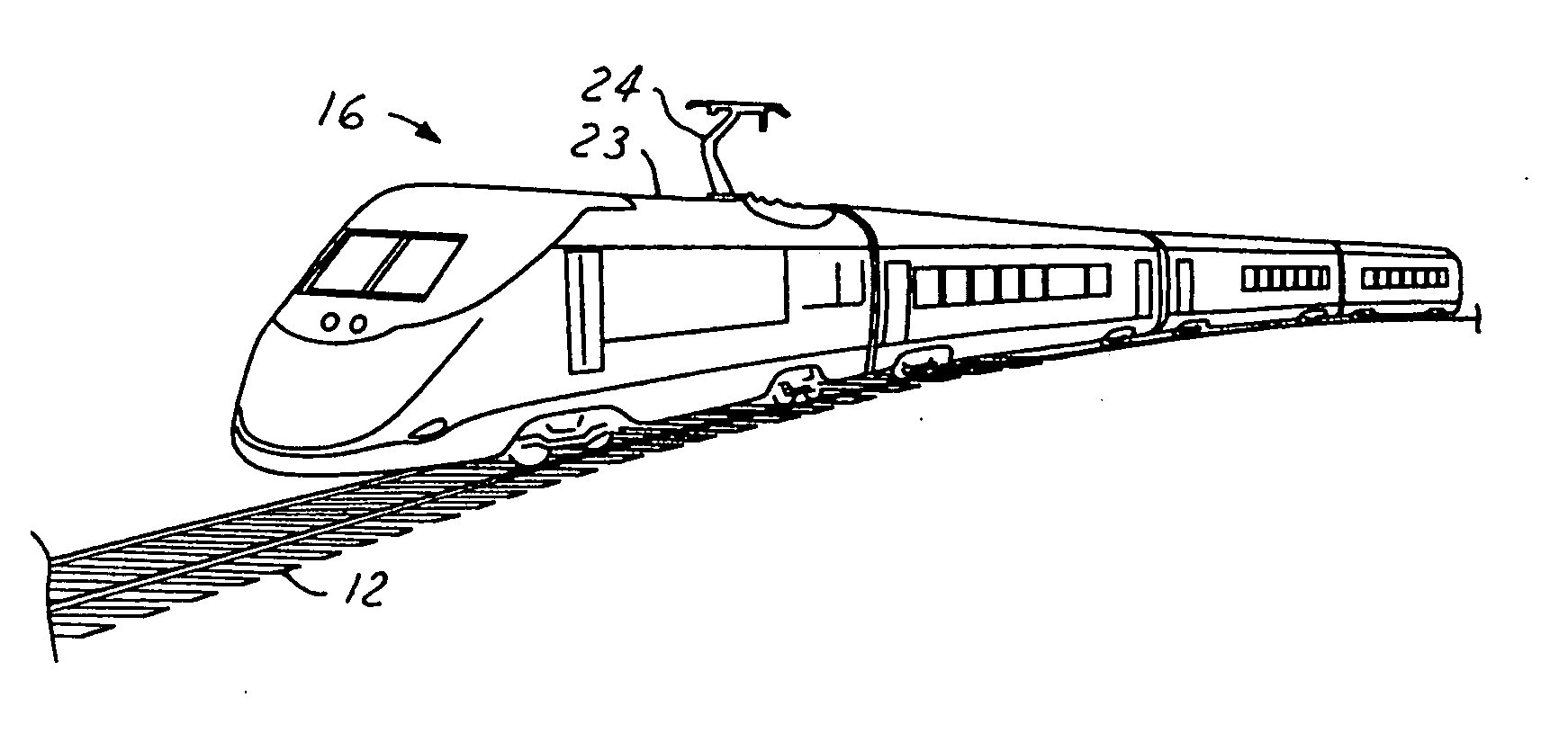
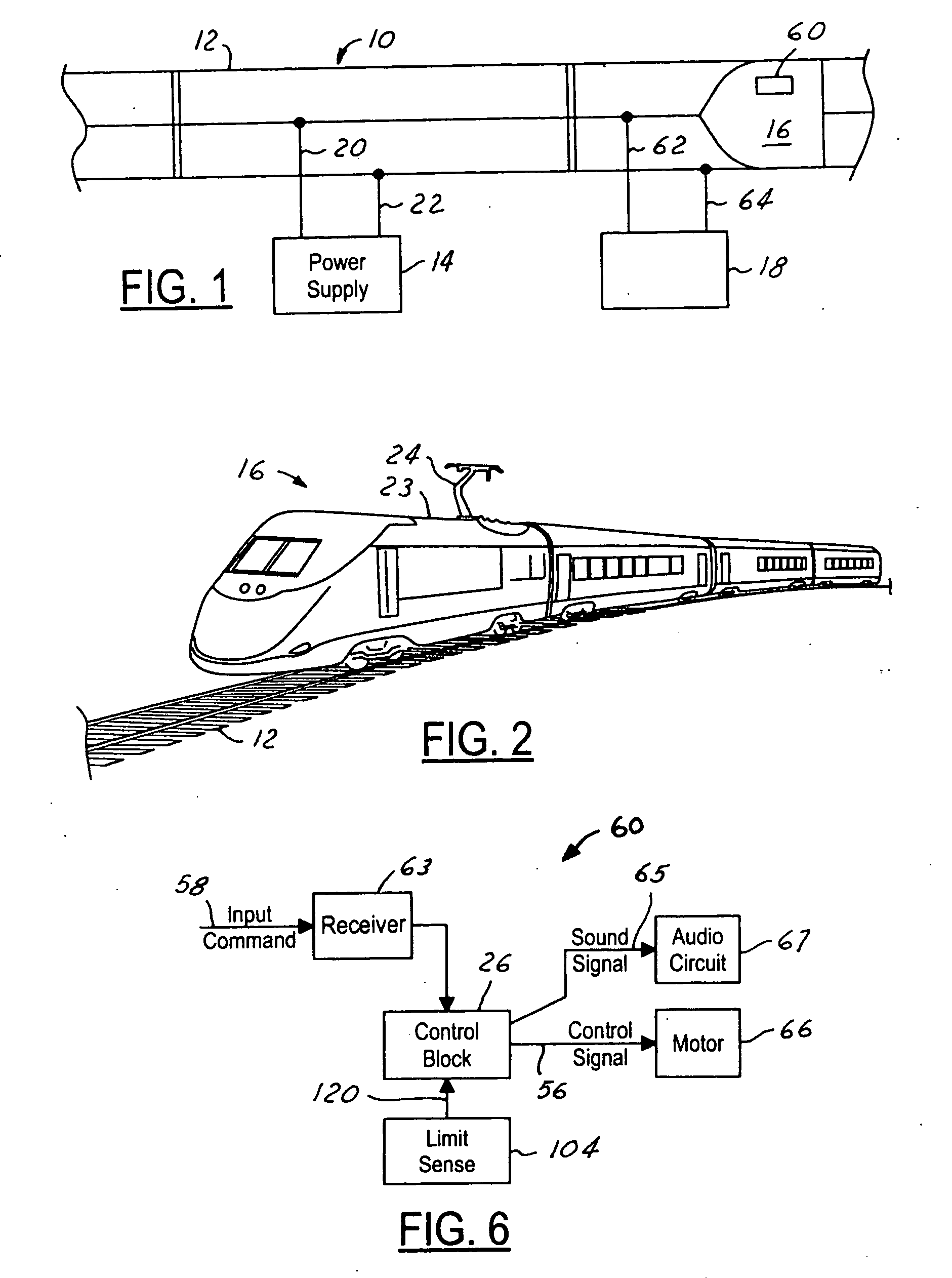
[0021]FIG. 1 shows a first exemplary embodiment of a model vehicle system, such as a model railroad system 10. The model vehicle system illustrated in the drawings and to be described herein is that of a model railroad. It should be noted, however, that the inventive model vehicle is not limited to such form or systems, but rather can be used in connection with any number of model systems. Accordingly, the use of a model railroad herein is for exemplary purposes only and is not meant to be limiting in nature.

[0022] Model train system 10 includes a track 12, a power supply 14, a train 16 and a control circuit 18. In an exemplary embodiment, track 12 is a three rail track. Power source 14 provides power to track ...


PUM


Abstract

A model vehicle, such as a model electric train, includes a model pantograph. The operation of the pantograph is automated using a motor, drive train, and control circuit. An upper articulating portion of the pantograph is mounting to the model vehicle using a breakaway assembly. The upper articulating portion may also be coupled to a drive motor via an elastic coupling permitting elastic movement of the upper portion independently of the drive motor.

Description

CROSS-REFERENCE TO RELATED APPLICATION [0001] This application claims priority pursuant to 35 U.S.C. § 119(e) to U.S. Provisional Application No. 60 / 575,267, filed May 28, 2004, which application is specifically incorporated herein, in its entirety, by reference.BACKGROUND OF THE INVENTION [0002] 1. Field of the Invention [0003] The present invention relates to electric-powered model vehicles, such as model trains, and more particularly, to a pantograph for a model train or other model vehicle. [0004] 2. Description of Related Art [0005] Various model trains and vehicles are known in the art, which model an actual or imaginary train or vehicle at a reduced scale. In a typical model layout, a model train having an engine is provided. The model train engine includes an electrical motor that receives power from a voltage that is applied to model railway tracks. A transformer is used to apply the power to the tracks, while contacts (e.g., a roller) on the bottom of the train, or metalli...

Claims


Application Information

Patent Timeline
Patent Type & Authority Applications(United States)
IPC IPC(8): B61D17/00
CPCA63H19/26A63H19/14
Inventor WEBSTER, RICHARD F.GREENING, STEVEN R.
Owner LIONEL LLC
Why Eureka
Try Eureka