
Motorized shade apparatus

a motorized shade and window covering technology, applied in the field of window coverings, can solve the problems of heavy installation, inconvenience, and disadvantages of current powered shade systems, and achieve the effect of convenient replacement of batteries and easy disassembly and reattachmen

Active Publication Date: 2020-08-25
BIEDERMANN DAVID T
View PDF12 Cites 1 Cited by
  • Summary
  • Abstract
  • Description
  • Claims
  • Application Information

AI Technical Summary

Benefits of technology

This patent describes a motorized window covering system that has attractive aesthetics and does not require an external power supply. The system includes a large capacity power supply that is not placed externally, but rather hidden within the system. The system can be installed in parts or modules, making it easier and more convenient to install. The power supply is a detachable and reattachable battery container that can be easily replaced without complex mechanisms or increased costs. The system also has a simplified method of installation, allowing for easy connection of the power supply and motor without the need for manual wiring. Overall, the motorized window covering system has a unique design and installation process that provides aesthetic appeal and flexibility in replacement components.

Problems solved by technology

Motorized shades are generally difficult and costly to install, especially when directly connected to household power as an electrician or other expert or professional is often required for installation.
Current powered shade systems, however, suffer from disadvantages, such as the following:
Installation of whole systems (designed to fit together prior to installation) can be heavy and awkward to install, often at unstable positions many feet above the floor.
All the above disadvantages increase the difficulty of installation and / or detract from the cycle life expectations and / or aesthetics of the motorized shade.

Method used


Image

  • Motorized shade apparatus
  • Motorized shade apparatus
  • Motorized shade apparatus

Examples


Embodiment Construction

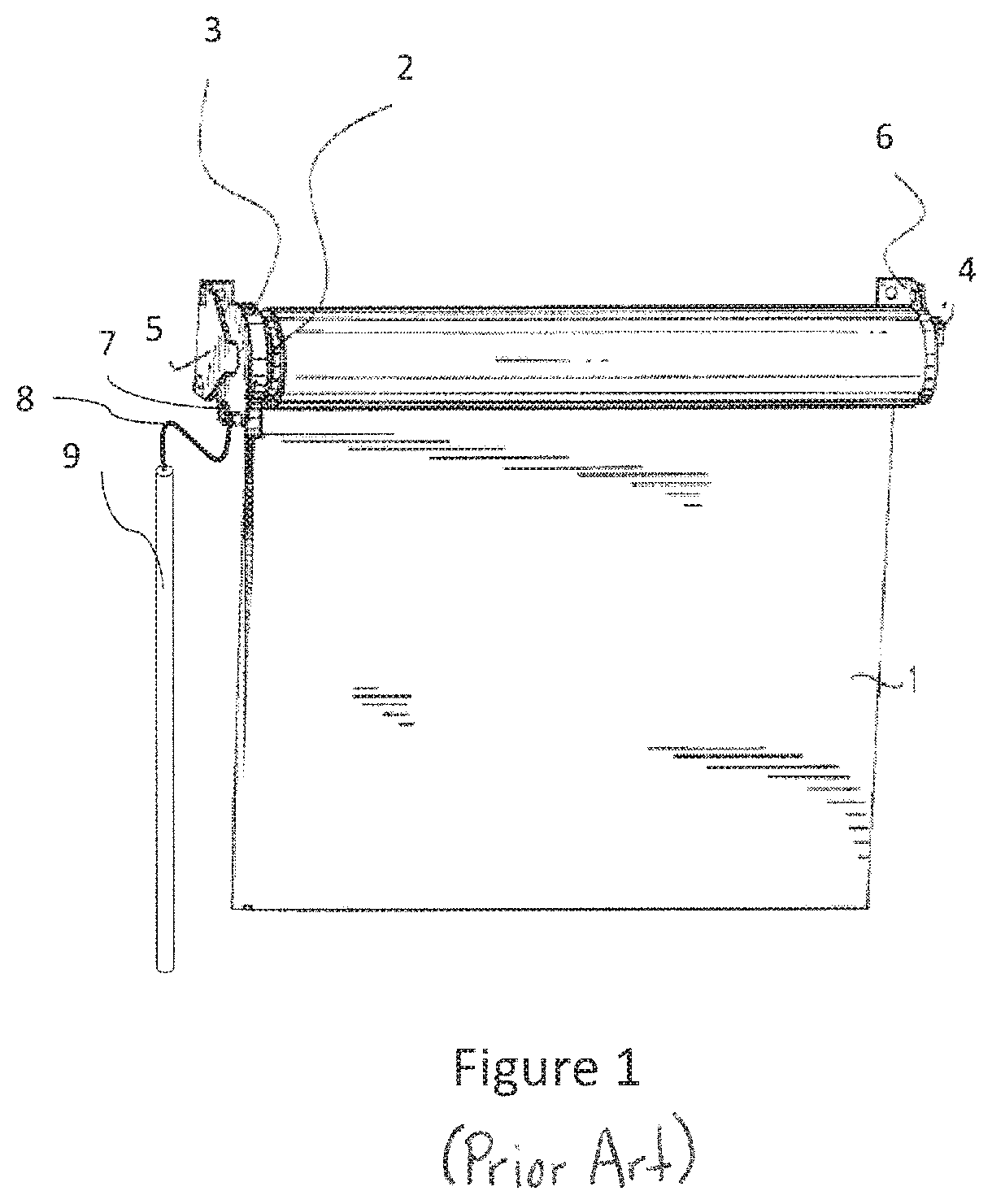
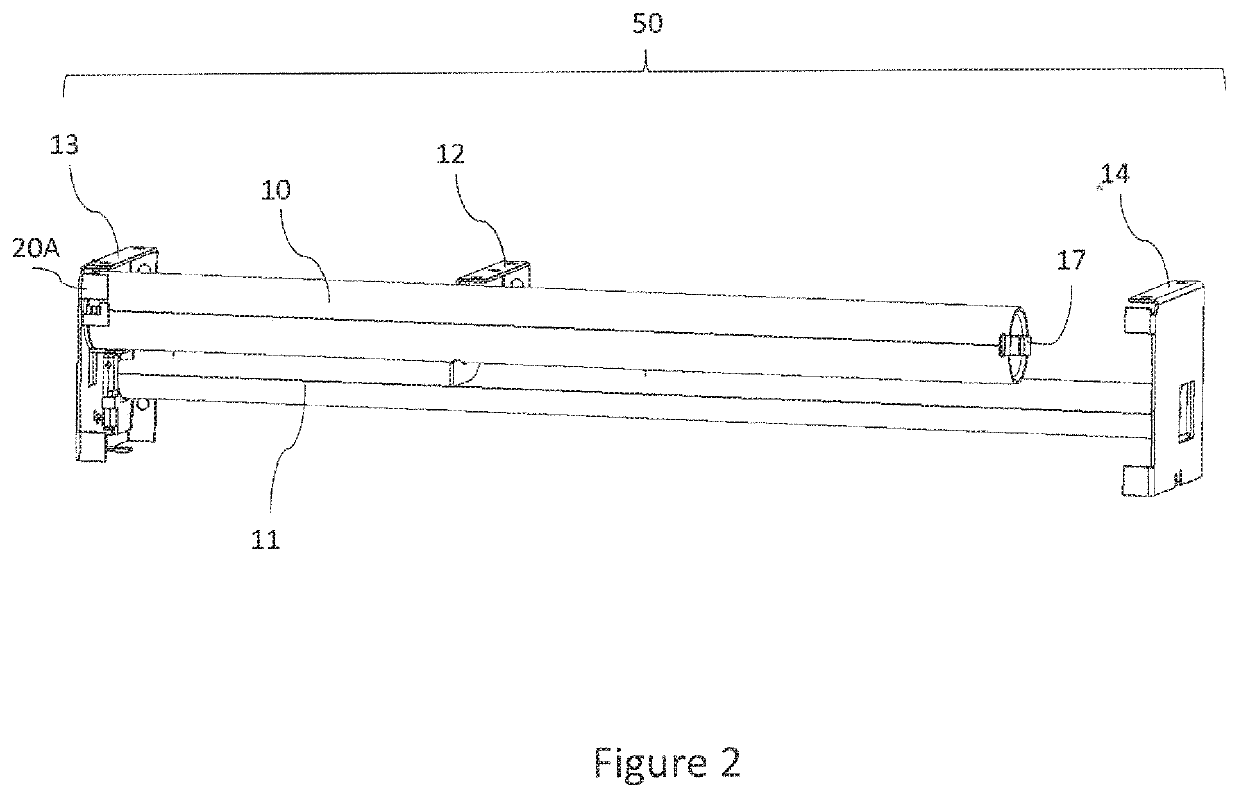
[0056]FIG. 1 shows an example of a prior art mounted motorized roller shade and assembly. In this example, shade material 1 is partially wound around the roller 2. Motor assembly 3 is inserted into one end of roller 2, and pivoting assembly 4 is inserted into the opposite end of the roller 2. Brackets 5, 6 support the shade 1 and roller assembly. The brackets 5, 6 and the pivoting assembly 4 may be constructed by techniques known in the art such as described in U.S. Pat. No. 4,729,418, which is hereby incorporated by reference. In this example, the wires from motor assembly 3 are manually connected via coupling 7 to wire 8 that connects to a power supply 9, which can be a tube of common batteries. Other power sources can be utilized, such as a transformer plugged into a standard household electric outlet. The height of the shade 1 may be adjusted by controlling the motor with a switch or radio remote control.

[0057]A motorized shade apparatus according to a preferred embodiment of th...


PUM


Abstract

A motorized shade apparatus for windows includes a power supply unit, such as a tube of large capacity batteries which may have long cycle life. All or all large system components can be hidden from view such as behind a valance or other covering. In an embodiment of the invention, the power supply current can be conveyed via integral connections with the motor / shade assembly. The system can be installed at-location in parts or modules. The valance, power supply, and motor assembly can be removed easily to replace components over time without complex mechanisms that increase cost or introduce disadvantages such as louder operational noises.

Description

CROSS REFERENCE TO RELATED APPLICATIONS[0001]This application claims priority to U.S. Provisional Patent Application No. 62 / 432,607, filed Dec. 11, 2016 and incorporated herein by reference.TECHNICAL FIELD AND BACKGROUND OF INVENTION[0002]The present invention relates to window coverings, such as curtains and shades. One embodiment of the invention comprises a motorized window covering apparatus comprising a detachable power supply unit.[0003]Window coverings, such as curtains and shades, are known in the art and are used to provide privacy, to limit the amount of light that can pass through a window and into a room or building, and to decorate rooms and provide aesthetic appearances. Roller shades and cellular shades are types of window coverings that comprise material that rolls up, or compresses onto itself. Generally, they are easy to install, are available in many colors and opacities, and are easy to maintain over their life. Also known in the art are motorized shades, which c...

Claims


Application Information

Patent Timeline
Patent Type & Authority Patents(United States)
IPC IPC(8): E06B9/42E06B9/50E06B9/72
CPCE06B9/72E06B9/42E06B9/50
Inventor BIEDERMANN, DAVID T.
Owner BIEDERMANN DAVID T
Learn More