Gastric tube placement indicator

a gastric tube and indicator technology, applied in the field of medical devices, can solve the problems of affecting the patient's respiratory system, affecting the patient's health, and affecting the patient's breathing, and causing the patient to suffer from a large amount of pain, and the time-consuming and labor-intensive nature of fluoroscopy and chest x-rays. disadvantages, and relatively expensiv

Inactive Publication Date: 2006-03-23
COVIDIEN AG
View PDF13 Cites 32 Cited by
  • Summary
  • Abstract
  • Description
  • Claims
  • Application Information

AI Technical Summary

Problems solved by technology

A common drawback when placing gastric feeding tubes either orally or nasally is the potential of passing the gastric feeding tube into the trachea, and then deeper into the respiratory tract and lungs, instead of properly in the stomach.
The consequence of having a gastric feeding tube placed into the respiratory system can lead to adverse medical complications, including pneumothorax, aspiration pneumonia or other complications that can damage the patient's respiratory system.
However, fluoroscopy and chest X-rays are disadvantageously time consuming, relatively expensive, and can expose the patient to high doses of radiation, while carbon dioxide detection machines used in capnography are relatively expensive and complex compared to other means of monitoring carbon dioxide.
Although such calorimetric indicators adequately detect the presence of carbon dioxide in the respiratory system during placement of the trachea tube, the use of conventional calorimetric indicators for use in indicating improper placement of the gastric feeding tube in the trachea is disadvantageous.
Because the lumen of a gastric tube is much smaller than the larger lumen of a trachea tube the capacity for facilitating sufficient airflow for the quick detection of carbon dioxide through the smaller lumen gastric feeding tube is limited.
As such, the use of a prior art carbon dioxide indicator 8 for gastric tube placement is problematic since the gastric feeding tube has a relatively smaller lumen than a trachea tube for respiratory applications that can create insufficient airflow through the larger dead space defined by the housing 88 for quick detection of carbon dioxide.
In particular, the positioning of such ports creates a perpendicular air flow pathway through the housing of the prior art carbon dioxide detector which is undesirable for gastric tube placement where the emphasis for quickly detecting the presence of carbon dioxide is critical.

Method used


Image

  • Gastric tube placement indicator
  • Gastric tube placement indicator
  • Gastric tube placement indicator

Examples


Embodiment Construction

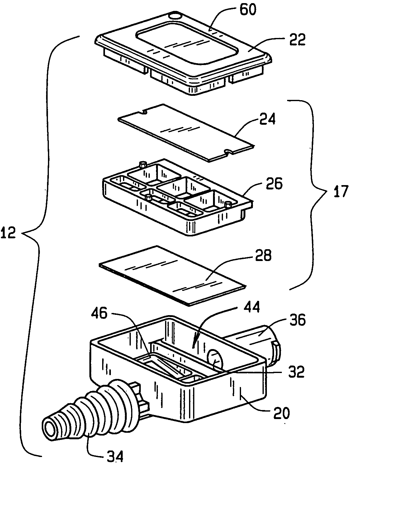
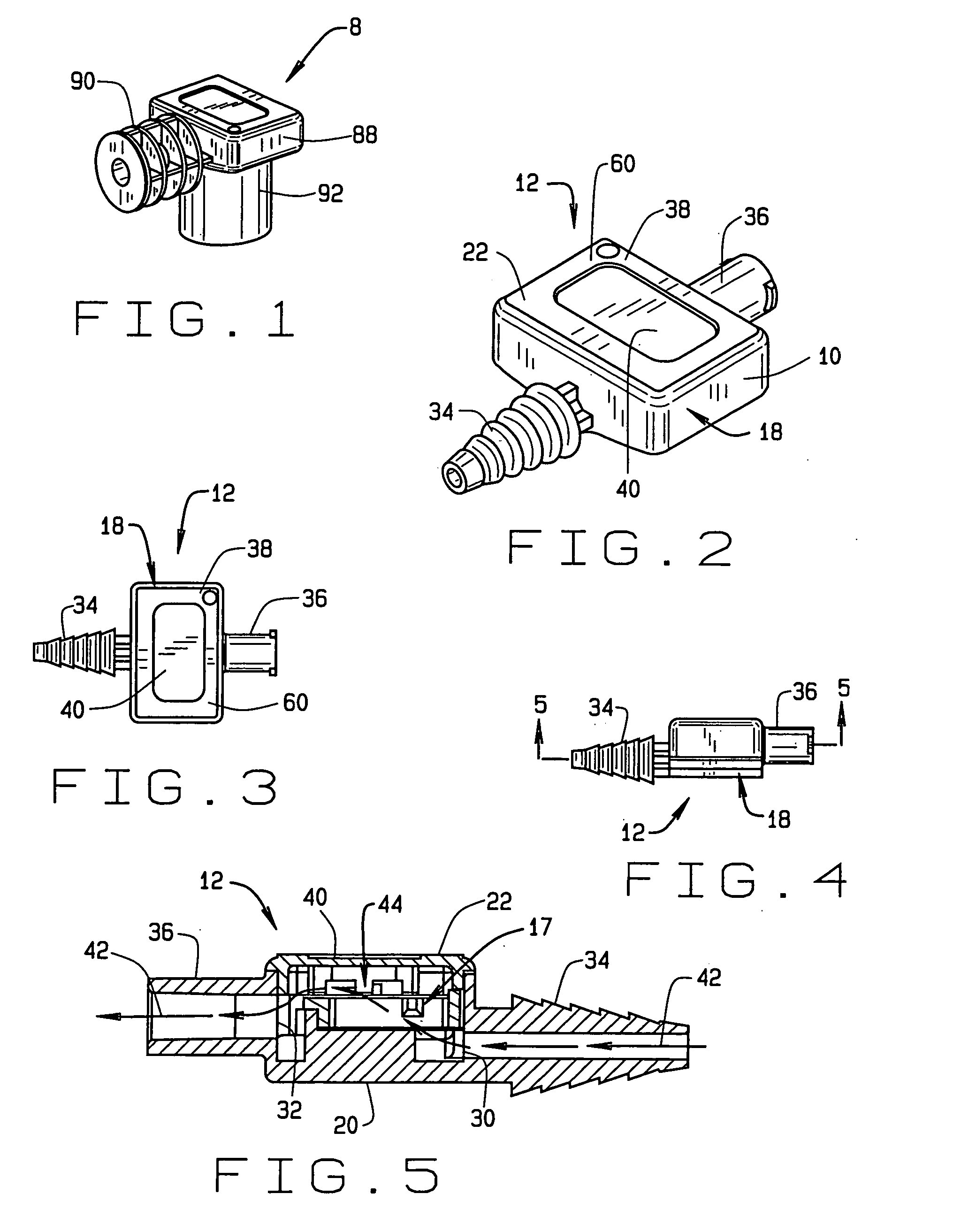
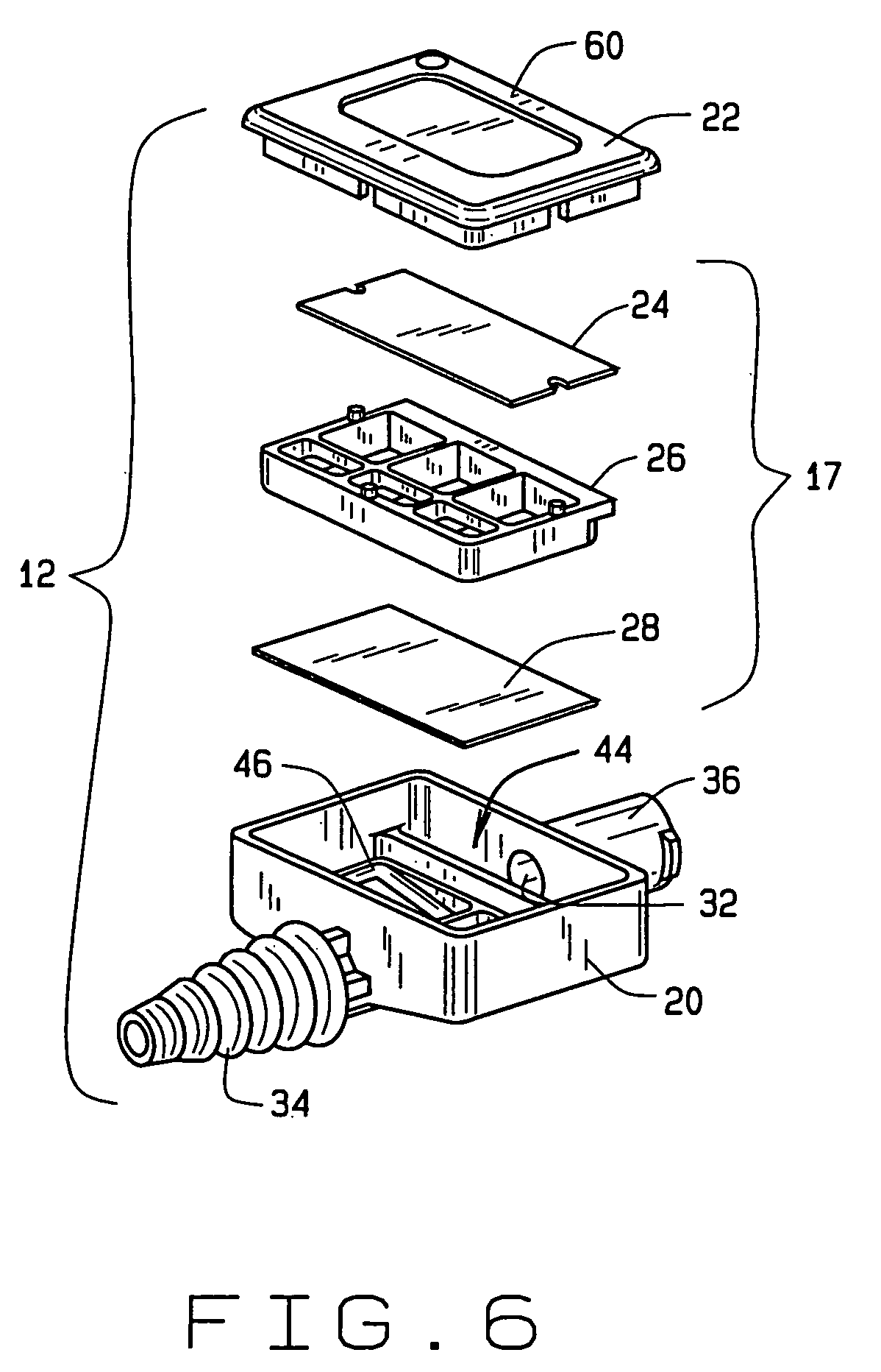
[0021] Referring to the drawings, a gastric tube placement device according to the present invention is illustrated and generally indicated as 10 in FIGS. 2-8. The gastric tube placement device 10 comprises a carbon dioxide (CO2) indicator 12 that encases a CO2 detector 17 in communication with a conventional Y-port connector 16 engaged to a gastric tube 14 for detecting the presence of carbon dioxide from a patient.

[0022] Referring to FIGS. 2-4, the CO2 indicator 12 comprises a rectangular housing 18 that encases the CO2 detector 17 for the detection of carbon dioxide that may enter the detector 17 when the gastric tube 14 is placed inside the patient. The housing 18 consists of a lower housing 20 engaged to an upper housing 22 that collectively defines a passageway 44 adapted to receive the CO2 detector 12 axially disposed therein. The housing 18 includes opposing first and second ports 30 and 32 wherein first port 30 is in communication with a barbed connector 34 for connection ...


PUM


Abstract

A gastric tube placement device having a carbon dioxide indicator is disclosed. The carbon dioxide indicator comprises a rectangular housing defining a chamber in communication with opposing ports that permits substantial axial flow through the chamber with a carbon dioxide detector disposed therein. A Y-port connector having first and second legs in communication with a main port with a gastric tube coupled to the inside of the connector is provided for insertion of the distal end of the gastric tube through the esophagus of the patient. The carbon dioxide indicator further comprises a carbon dioxide detector disposed inside the rectangular housing which is configured to minimize the dead space inside the housing and facilitates a substantially axial airflow through the carbon dioxide detector when a syringe or similar air-evacuating device is engaged to the rectangular housing and draws air from the housing.

Description

CROSS-REFERENCE TO RELATED APPLICATION [0001] This continuation-in-part application claims the benefit of U.S. Non-Provisional Patent Application entitled “Gastric Tube Placement Indicator”, Ser. No. 10 / 945,758, filed Sep. 21, 2004, which is herein incorporated by reference.FIELD OF THE INVENTION [0002] The present invention relates to a medical device employed to verify placement of a gastric feeding tube in a patient, and more particularly to a gastric tube placement device for the detection of carbon dioxide through a gastric feeding tube. BACKGROUND OF THE INVENTION [0003] It is known in the art that gastric feeding tubes may be employed for feeding patients requiring nutritional support. Such gastric tubes can be inserted into a patient either orally or nasally. In practice, a gastric feeding tube is inserted either into the mouth or nose of the patient and through the patient's pharynx until it reaches the esophagus. [0004] A common drawback when placing gastric feeding tubes ...

Claims


Application Information

Patent Timeline
Patent Type & Authority Applications(United States)
IPC IPC(8): A62B9/06A61M16/00
CPCA61B17/3415A61B19/46A61B2019/4836A61M2016/0413A61J2015/0088A61J15/0003A61J15/0026A61J2205/20G01N31/22A61J15/0088A61B90/06A61B2090/0807
Inventor FLYNN, DANIEL P.FOURNIE, GLENN G.MEIER, KEVIN C.TRELFORD, PAUL
Owner COVIDIEN AG
Why Eureka
Try Eureka