

Sump assembly of dishwasher
- Summary
- Abstract
- Description
- Claims
- Application Information
AI Technical Summary
Benefits of technology
Problems solved by technology
Method used
Image

Examples
Embodiment Construction
[0027] Reference will now be made in detail to the preferred embodiments of the present invention, examples of which are illustrated in the accompanying drawings. Wherever possible, like reference numbers will be used throughout the drawings to refer to the same or similar parts.
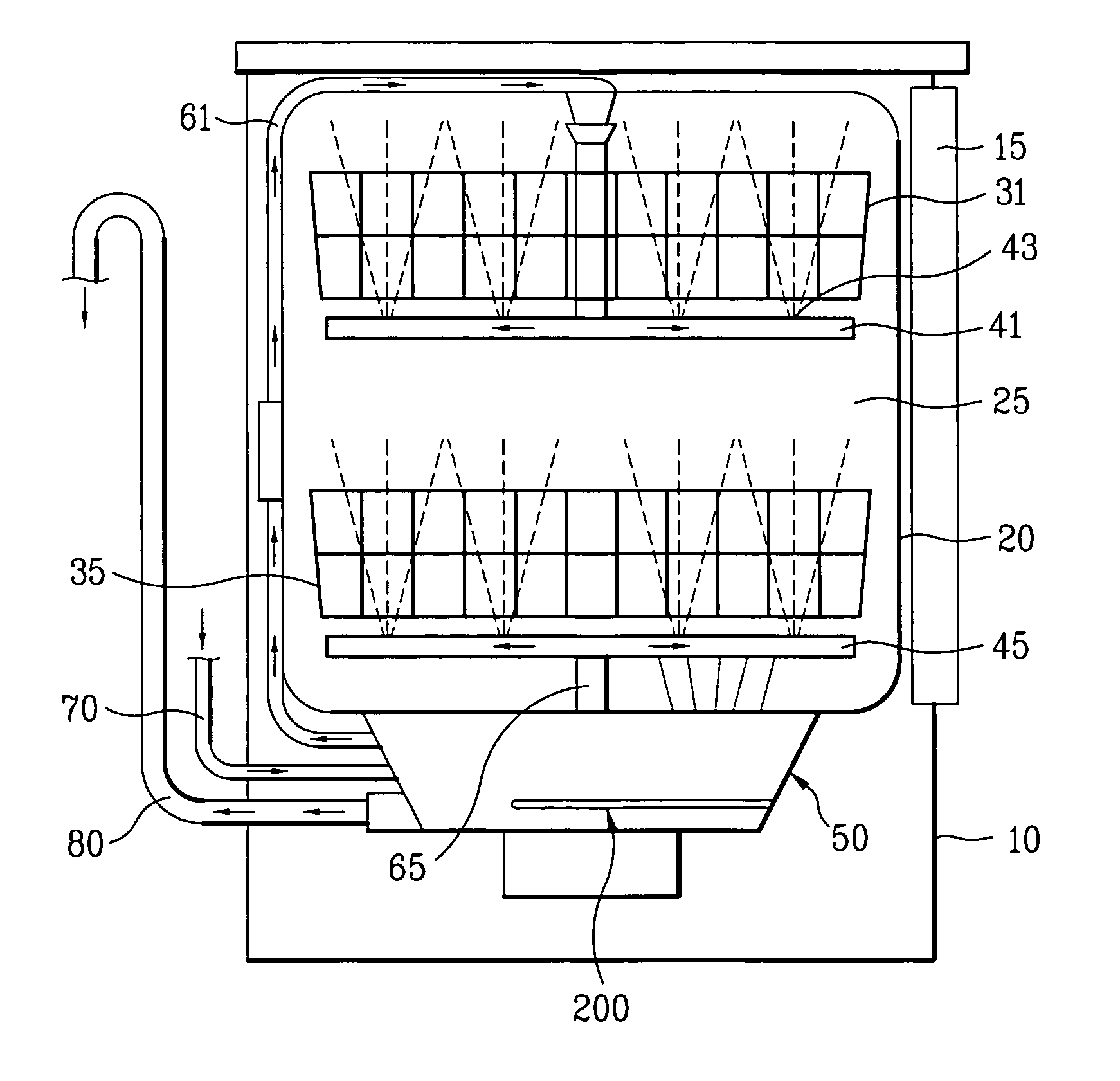
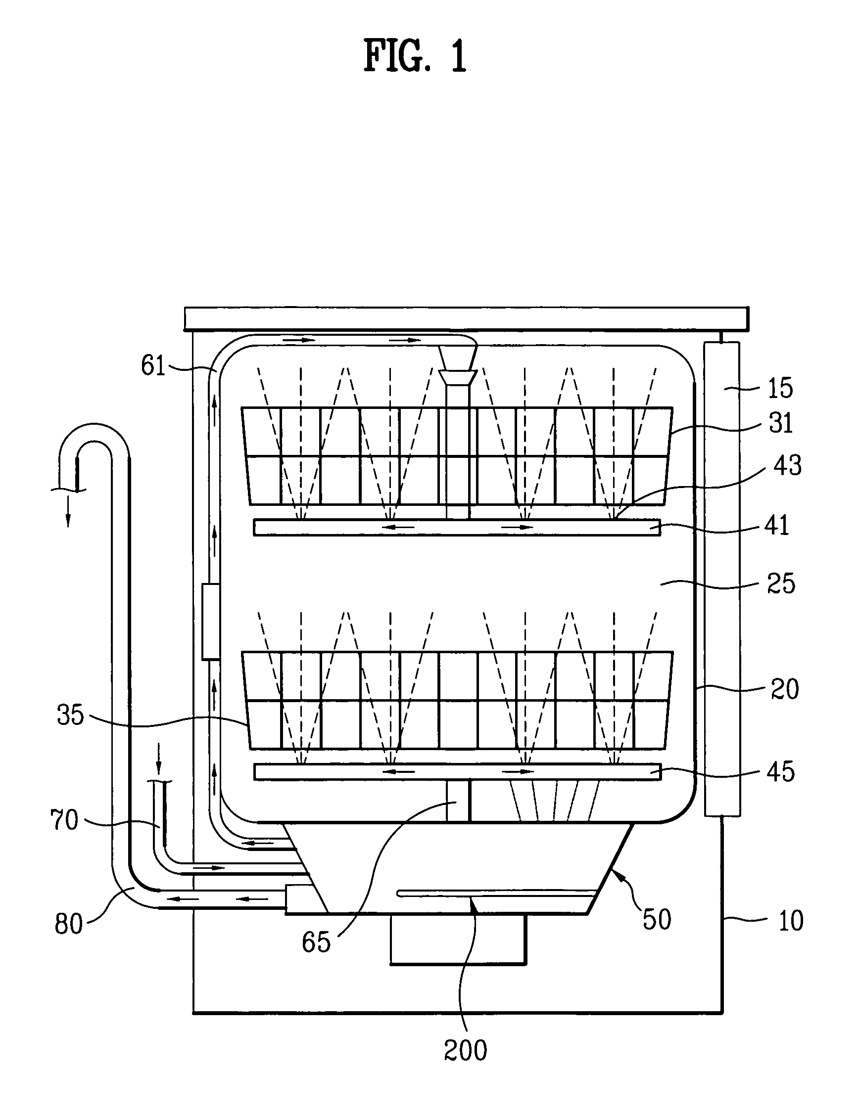
[0028] Referring to FIG. 1, illustrating a dishwasher according to the present invention, a tub20 is provided within a case 10 forming an exterior of a dishwasher, and a door 15 opening / closing the tub is provided to one side of the case. A washing chamber 25 for accommodating articles to be washed is defined by the tub 20, which houses at least one rack, e.g., upper and lower racks 31 and 35, for loading the articles and at least one spray arm, e.g., upper and lower spray arms 41 and 45, which are rotatable when spraying water through a set of spray nozzles 43 arranged adjacent each rack.
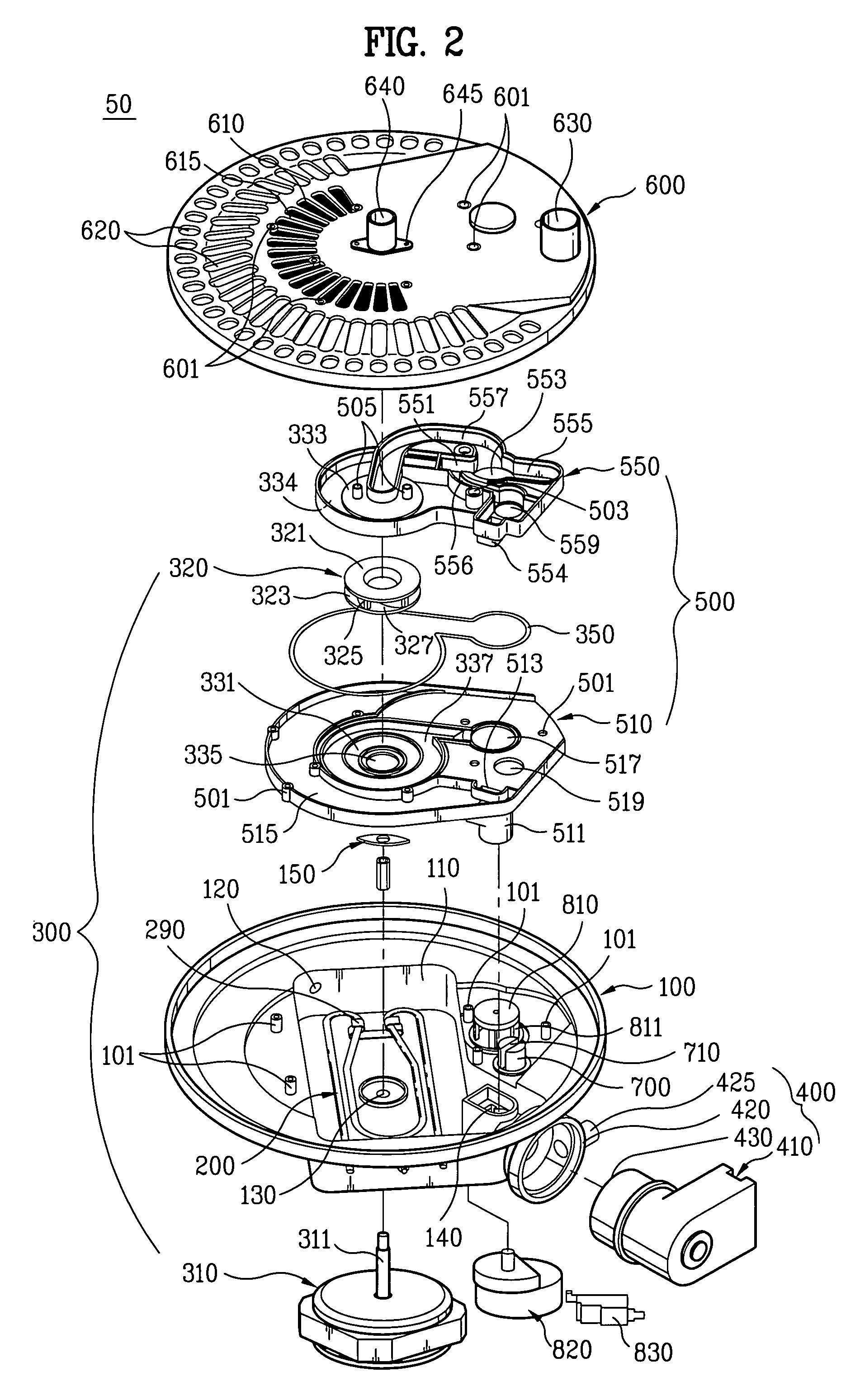
[0029] A sump assembly 50 for supplying water to the upper and lower arms 41 and 45 is provided within the case 10, and...
PUM
 Abstract
Description
Claims
Application Information