Self-draining vacuum breaker

Inactive Publication Date: 2006-03-23
YANG YUNG FANG
View PDF4 Cites 2 Cited by
  • Summary
  • Abstract
  • Description
  • Claims
  • Application Information

AI Technical Summary

Benefits of technology

[0006] The primary objective of the present invention is to provide an improved self-draining vacuum breaker, which is structurally simple and durable.
[0007] The foregoing objective of the present invention is attained by the improved self-draining vacuum breaker, which is connected between an outfall and a hose and comprised of a tubular first valve, an internally-stepped tubular second valve, a circular diaphragm, a movable stopper, and a spring. The first valve includes an inlet formed at an end and connected with the outfall, at least one slot formed at a bottom side of the inlet, and a coupling end formed at the other end thereof and having an external thread. The second valve includes a coupling portion formed at an end thereof and having a larger diameter than that of the coupling end of the first valve, and an outlet formed at the other end thereof for connecting a hose. The coupling portion of the second valve has a thread hole for threadedly connecting the coupling end of the first valve and a recess formed in th

Problems solved by technology

Further, if the automatic sprinkler system is located at high latitude regions and once the temperature suddenly drops to the freezing point, the remanent water in the hose will freeze to obstruct the hose and to potentially further rupture the hose due to the expansion incurred while the water transforms into ice.
Hence, the user has to repair the hose or reinstall the hose underground, thereby causing a great trouble for the user.
However, the circular diaphragm 2 is held in position merely by the two valv

Method used


Image

  • Self-draining vacuum breaker
  • Self-draining vacuum breaker
  • Self-draining vacuum breaker

Examples


Embodiment Construction

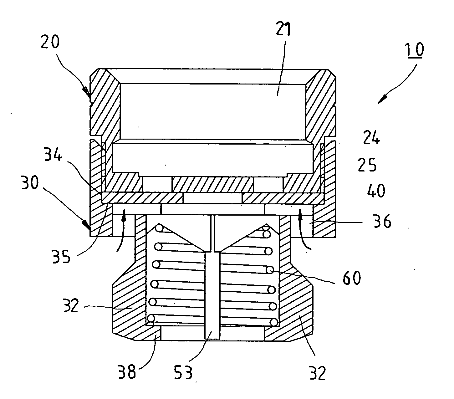
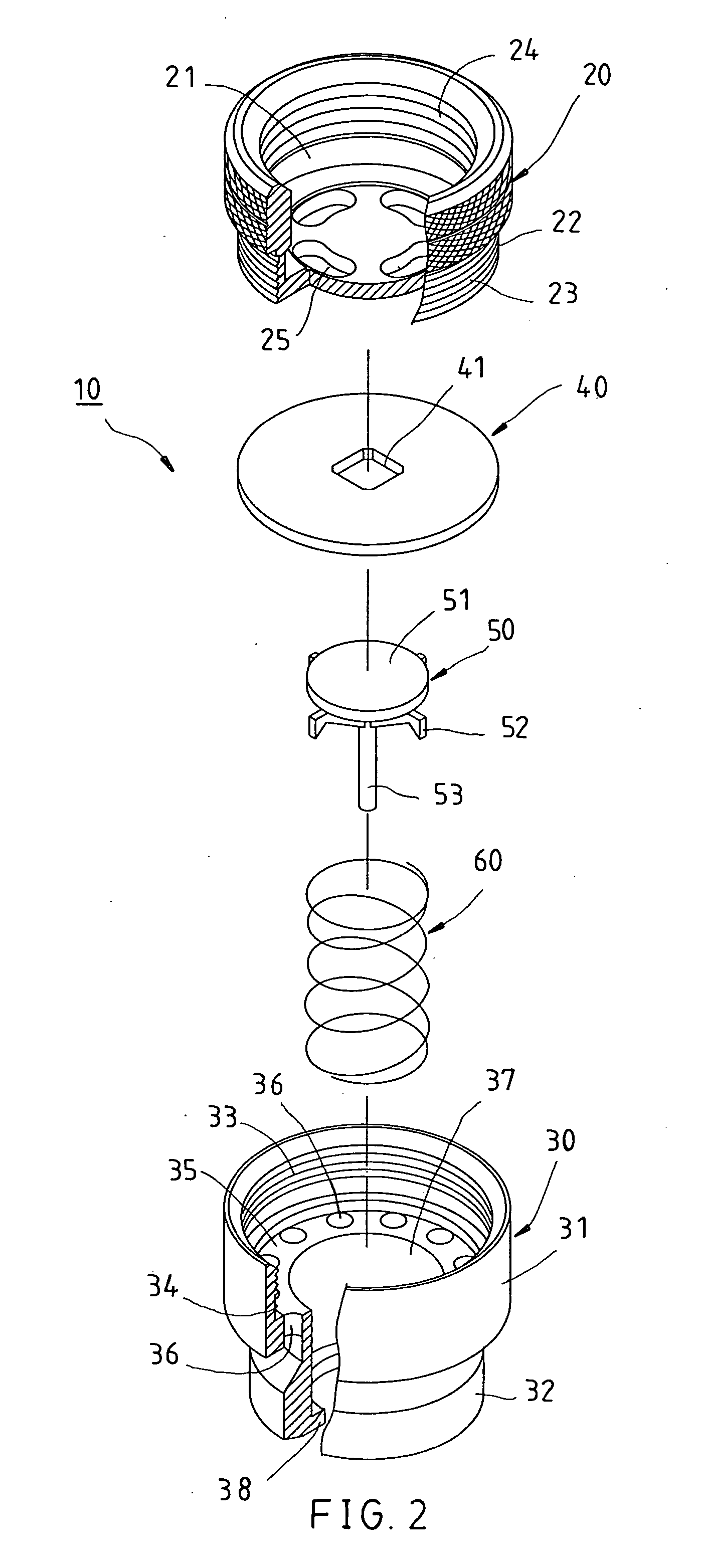
[0013] Referring to FIGS. 2-4, a self-draining vacuum breaker 10 constructed according to a preferred embodiment of the present invention is comprised of a tubular first valve 20, an internally-stepped tubular second valve 30, a circular diaphragm 40, a movable stopper 50, and a spring 60.

[0014] The first valve 20 includes an inlet 21 formed at an end thereof for connecting a faucet (not shown) or an outfall (not shown) and having an internal thread 24, and a coupling end 22 formed at the other end thereof and having an external thread 23. The inlet 21 is provided with four slots 25 formed at a bottom side thereof.

[0015] The second valve 30 includes a coupling portion 31, which is formed at an end thereof and which diameter is larger than that of the coupling end 22, and an outlet 32 formed at the other end thereof for connecting a hose (not shown). The coupling portion 31 has a thread hole 33 axially extending inwards for threadedly connecting the coupling end 22, and an annular ...


PUM


Abstract

A self-draining vacuum breaker includes a tubular first valve, an internally-stepped tubular second valve, a circular diaphragm, a movable stopper, and a spring. The first valve includes an inlet formed at an end and thereof, and a coupling end formed at the other end thereof and having an external thread. The second valve includes a coupling portion formed at an end thereof and having a thread hole, and an outlet formed at the other end thereof, and a recess formed in the thread hole for jamming said circular diaphragm and having an outlet hole. A stepped portion is formed between the thread hole and the outlet hole, having a plurality of vent holes running therethrough for communicating with outside. Therefore, when the self-draining vacuum breaker is connected between an outfall and a hose, the air can be brought into the hose to eliminate the vacuum.

Description

BACKGROUND OF THE INVENTION [0001] 1. Field of the Invention [0002] The present invention relates generally to drainage system, and more particularly to a self-draining vacuum breaker, which can immediately eliminate the vacuum formed in the hose and further drain the water remaining in the hose. [0003] 2. Description of the Related Art [0004] There are automatic sprinkler systems mounted in most of the common farms, greenhouses, and courtyards for regularly providing the plants with water. When the automatic sprinkler system is working, the water flows out of a faucet, passes by the underground hose, then reaches the sprinkler in the garden, and finally sprays out through the sprinkler. When the sprinkler finishes the work and turns off the faucet to stop watering, there is still water remaining in the hose. Meanwhile, the faucet is sealed to generate vacuum in the hose, thereby preventing the remaining water from drainage. Further, if the automatic sprinkler system is located at h...

Claims


Application Information

Patent Timeline
IPC IPC(8): F16K24/00
CPCF16K24/06E03B7/10E03C1/1225Y10T137/3331
Inventor YANG, YUNG-FANG
Owner YANG YUNG FANG
Why Eureka
Try Eureka