
Adjustable hanger

Inactive Publication Date: 2006-03-23
DARRE LAURA
View PDF23 Cites 13 Cited by
  • Summary
  • Abstract
  • Description
  • Claims
  • Application Information

AI Technical Summary

Benefits of technology

[0007] The present invention is an adjustable wall hanger having a wide range of height adjustments which is not dependent up

Problems solved by technology

However, it often happens that misalignment is substantial, and cannot thus be remedied.
In such case, the hanger itself must be repositioned, necessitating creating a new nail hole, and leaving an unsightly empty hole in the wall.
Such an arrangement permits minute changes in the height of the hook, eliminating the incremental steps of the Beyer and Eysmann arrangements but the amount of change is limited by the length of the bolt.
In the prior art, as exemplified by the foregoing patents, vertical adjustment is generally achieved in incremental steps, with attendant limitation on achieving the exact picture height desired.

Method used


Image

  • Adjustable hanger
  • Adjustable hanger

Examples


Embodiment Construction

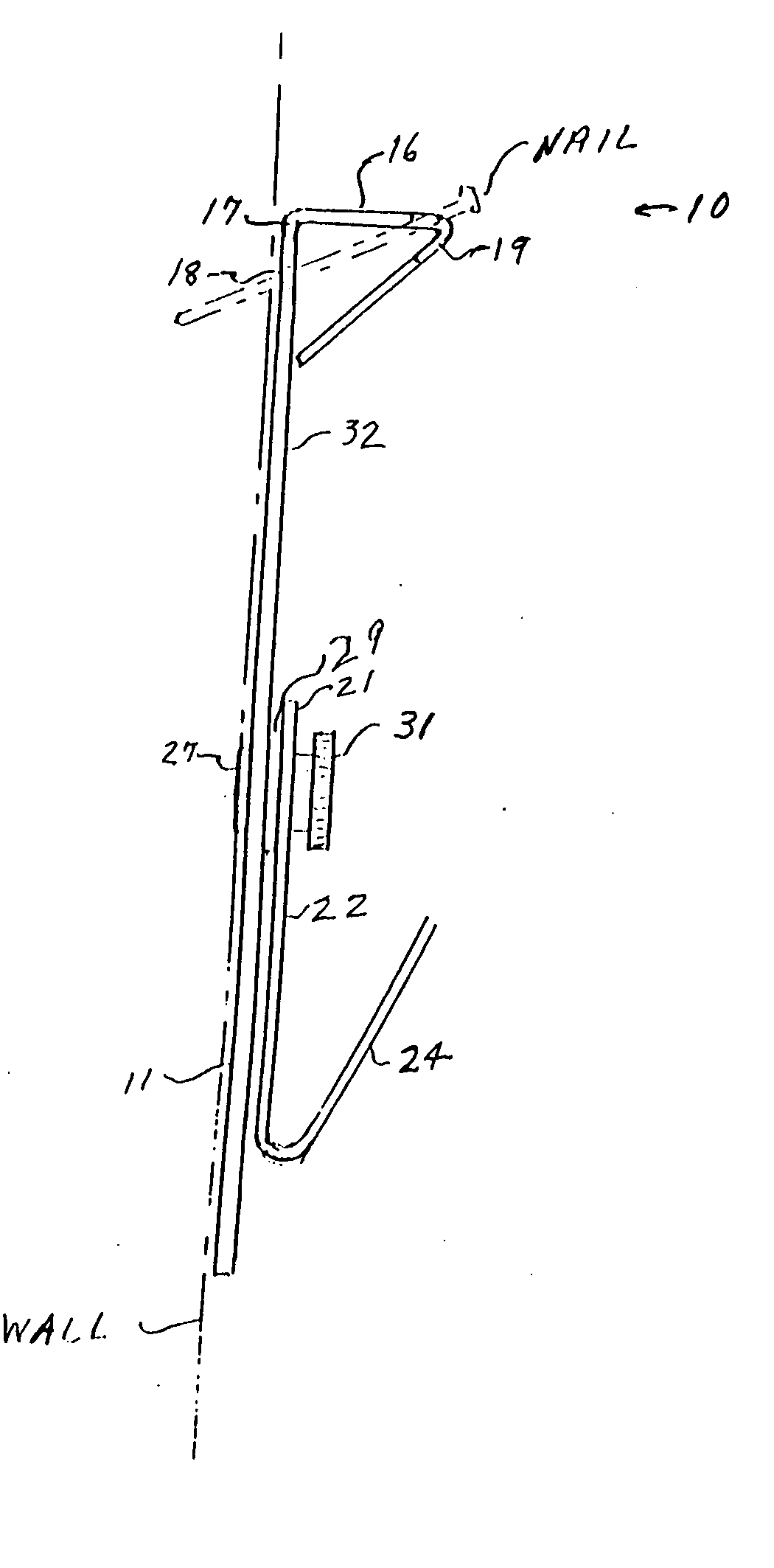
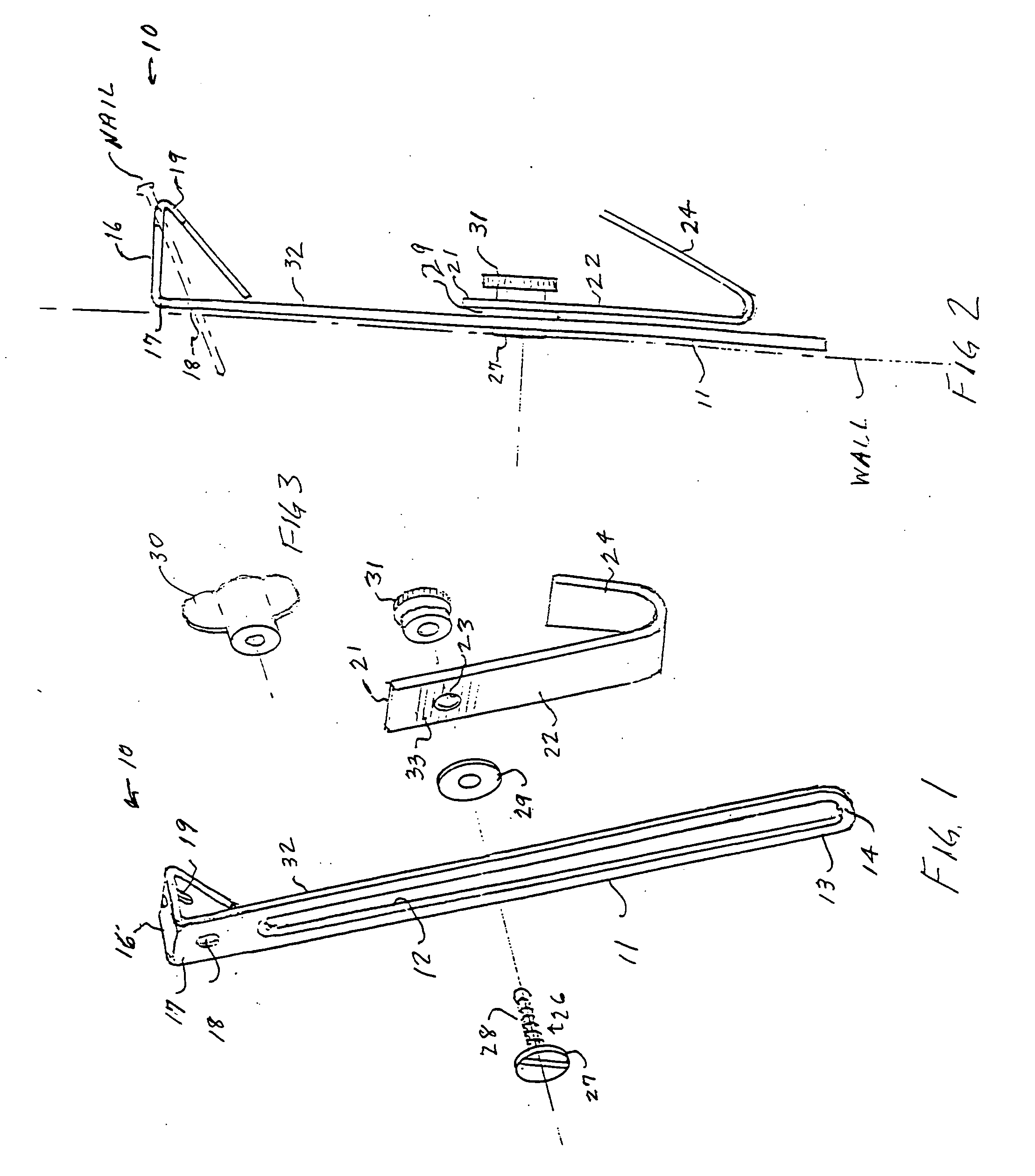
[0016] As seen in FIGS. 1 and 2, the adjustable hanger 10 of the present invention comprises an elongated support bracket 11 of brass, aluminum, or other suitable material, preferably, but not necessarily, of a metal having sufficient strength to accommodate reasonably heavy loads. Extending along the length of bracket 12 is a longitudinal slot 12, closed at the bottom or distal end 13 by a cross-piece 14. A typical mounting triangle 16 is at the top or proximal end 17, the lower portion of which closes slot 12. A pair of holes 18 and 19, vertically offset from each other as shown are formed in different legs of mounting triangle 16 for allowing a hanger nail to be driven into a wall in a slanted or toed orientation, as shown in FIG. 2, to mount bracket 11 to the wall. While a mounting triangle is shown, other mounting means known in the art, including a simple mounting hole, may be used.

[0017] A hook member 21 of suitable material such as brass, aluminum, or other material, prefer...


PUM


Abstract

An adjustable hanger for hanging pictures, tools, or the like has an elongated, slotted bracket member having a wall mounting portion at one end thereof. A hanger hook member has a vertical portion with a bolt hole adjacent one end and is adapted to be positioned anywhere along the bracket by means of a bolt member and a resilient washer. The surfaces of the bracket and the vertical portion of the hook member may be roughened or striated to insure better purchase of the resilient washer between those two members when compressed by the action of the bolt member.

Description

RELATED APPLICATIONS AND CLAIM OF PRIORITY [0001] The present invention is the subject of U.S. Provisional Patent Application Ser. No. 60 / 572,831, filed May 20, 2004, by the present inventor, and in view of which priority is claimed for the present application.FIELD OF THE INVENTION [0002] This invention relates to hangers for pictures, tools, utensils, and, more particular, to an adjustable hanger. BACKGROUND OF THE INVENTION [0003] While the present invention, as will be apparent hereinafter, is applicable to hanging a wide range of articles, the following discussion will be in the context of hanging pictures although it is not intended that the invention be limited thereto. Wall hanging of pictures, such as in the home, is accomplished most often by use of a metal hook having a vertical shank, and a roughly triangular nail holder at the top of the shank which permits a nail to be driven into the wall in an angular or toed orientation. Where a particular pattern of framed pictures...

Claims


Application Information

Patent Timeline
IPC IPC(8): A47G1/24
CPCA47G1/202B25H3/006
Inventor DARRE, LAURA
Owner DARRE LAURA
Learn More