Redundant radio frequency network having a roaming terminal communication protocol

a radio frequency network and communication protocol technology, applied in the field of redundant communication network having a polling protocol, can solve the problems of network and protocol problems, battery-powered roaming terminals, and the range of wall-socket-powered rf base stations cannot match the increased range of rf base stations

Inactive Publication Date: 2006-03-23
INNOVATIO IP VENTURES
View PDF32 Cites 25 Cited by
  • Summary
  • Abstract
  • Description
  • Claims
  • Application Information

AI Technical Summary

Problems solved by technology

However, when faced with hundreds of roaming terminals which move in and out of the range of multiple RF base stations, networking and protocol problems emerge.
To solve these problems, attempts have been made to decrease the number of base stations by increasing the base stations range; however, the range of the often battery-powered roaming terminals cannot match the increased range of the wall-socket-powered RF base stations.
Moreover, by increasing the range, collisions due to propagation times also increase, slowing down the overall communication time.
Although this solves the range problems associated with a single RF base station, additional problems result.
First, roaming terminals which are in an overlapping range region between RF base stations communicate with one base station but receive unwanted communication from the other.
Second, each roaming terminal often receives unwanted communication from other roaming terminals.
Because of these encounters, each roaming terminal often transmits over the “hidden” communications causing collisions.
Additionally, as the number of RF base stations increase, communication pathways from the source to destination become more and more complex.
In an environment in which the spatial layout of the network continually changes, however, determining the most efficient pathways becomes very difficult.

Method used


Image

  • Redundant radio frequency network having a roaming terminal communication protocol
  • Redundant radio frequency network having a roaming terminal communication protocol
  • Redundant radio frequency network having a roaming terminal communication protocol

Examples


Embodiment Construction

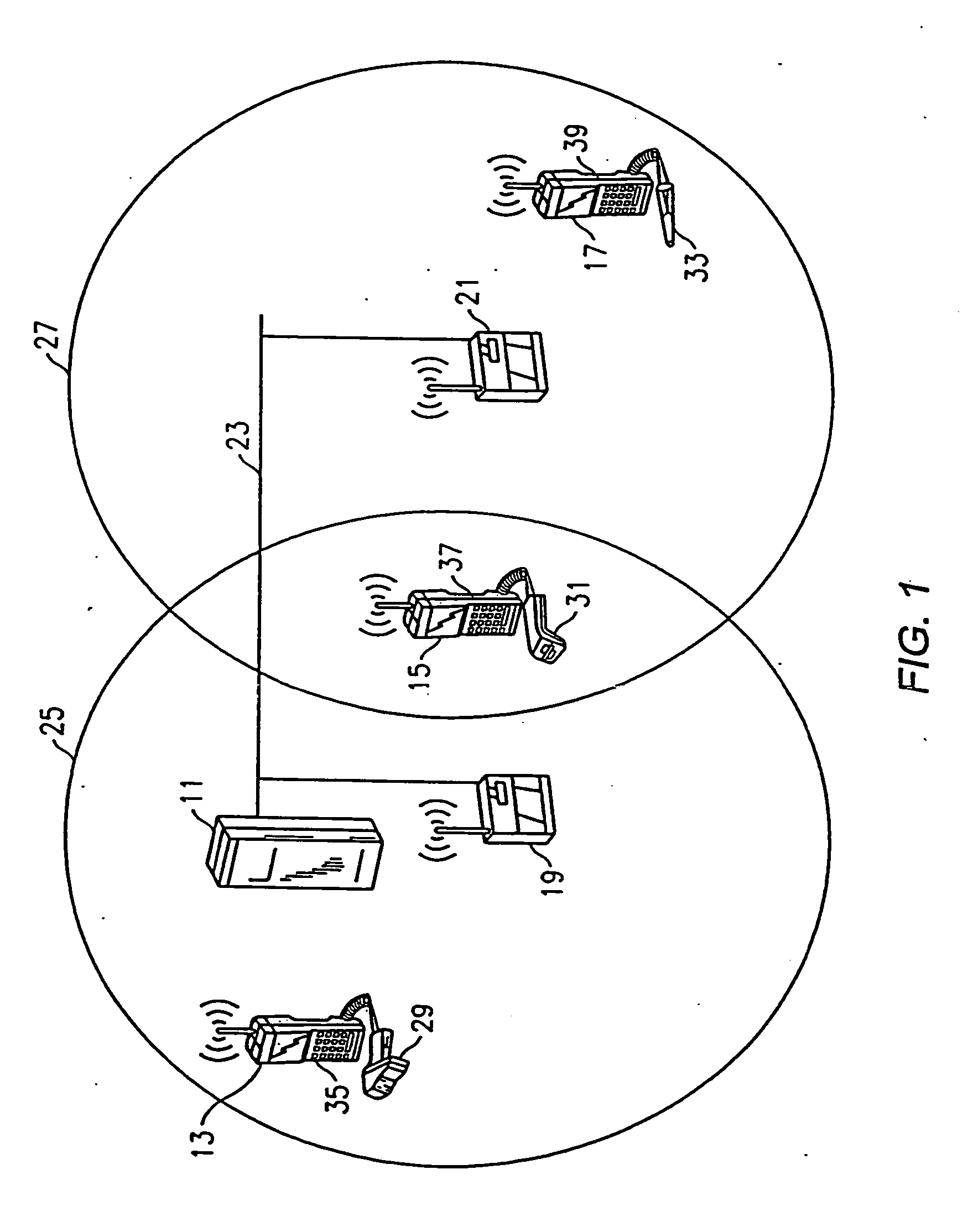
[0031]FIG. 1 is a diagram which illustrates the basic communication pathways and spatial relationships between a host computer, base stations and roaming terminals of the present invention. Particularly, a host computer 11 and roaming terminals 13, 15 and 17 indirectly communicate through base stations 19 and 21. The base stations 19 and 21 receive communications via one link medium and relay those communications along another. Particularly, a “hard-wired” connection such as an IEEE 802.3 (ethernet) interface provides a link 23 to host computer 11, while radio frequency (RF) transmission provides the link to the roaming terminals 13, 15 and 17.

[0032] If the remote terminals 13, 15 and 17 are within the RF range of each other, they can use direct RF transmission as the link. If they are not within RF range, an indirect communication link must be found through the base stations 19 and 21. The RF range of the base stations 19 and 21 is illustrated in FIG. 1 by the respective circular ...


PUM


Abstract

Disclosed herein is a redundant network and communication protocol at least including host computers, RF base stations, and roaming terminals. The network may utilize a polling communication protocol such that under heavy traffic conditions, a roaming terminal wishing to initiate communication may be required to determine whether the channel is clear by listening for an entire interpoll gap time. When a hidden terminal is communicating, the roaming terminal may conclude that the communication is taking place upon receiving a polling frame directed to the hidden terminal from the normally silent base station. Inherent redundancy techniques may be used with a spanning tree approach for determining the most efficient pathways from a source to a destination and ensuring that the network adapts to spatial changes or breakdowns within the network.

Description

CROSS REFERENCE TO RELATED APPLICATIONS [0001] The present application is a continuation of U.S. application Ser. No. 09 / 849,776 filed May 4, 2001 which is a continuation of U.S. application Ser. No. 09 / 482;197, filed Jan. 12, 2000, (Attorney Docket No. 37882AAYA) which is a continuation of U.S. application Ser. No. 08 / 941,496 filed Sep. 30, 1997 (Attorney Docket No. 37882AAY), now abandoned, which is a continuation of U.S. application Ser. No. 08 / 270,533 filed Jul. 5, 1994, now U.S. Pat. No. 5,673,031 issued Sep. 30, 1997 (Attorney Docket No. 37882AXX). Said application Ser. No. 08 / 270,533 is hereby incorporated herein by reference in its entirety including Appendices A and B. [0002] Said application Ser. No. 08 / 270,533 is a continuation-in-part of U.S. application Ser. No. 07 / 802,348, filed Dec. 4, 1991 (Attorney Docket No. 91 P 1189; DN37882AX) which is a continuation-in-part of U.S. application Ser. No. 07 / 790,946, filed Nov. 12, 1991 (Attorney Docket No. 91 P 1130; DN37882A), n...

Claims


Application Information

Patent Timeline
Patent Type & Authority Applications(United States)
IPC IPC(8): H04L12/413H04L12/403H04J3/16H01Q1/00H04L1/00H04L12/28H04L12/56H04L29/06H04M1/73H04W40/04H04W40/24H04W40/30H04W40/36H04W74/08
CPCH01Q1/007H04L69/14H04L12/4625H04L29/12216H04L45/00H04L61/2007H04W36/00H04W40/04H04W40/246H04W40/248H04W40/30H04W40/36H04W52/0229H04W74/06H04W74/0808H04W74/0816H04W80/00H04L1/0025Y02D30/70H04L61/5007
Inventor MEIER, ROBERT C.
Owner INNOVATIO IP VENTURES
Why Eureka
Try Eureka