Tunable laser source

Inactive Publication Date: 2006-03-23
YOKOGAWA ELECTRIC CORP
View PDF5 Cites 2 Cited by
  • Summary
  • Abstract
  • Description
  • Claims
  • Application Information

AI Technical Summary

Benefits of technology

[0029] According to the tunable laser source, since the branch ratio of the branch section is different depending on the wavelength, the light intensity ratio of the maximum light intensity and the minimum light intensity of the other branched light incident on the light receiving section is smaller than the light intensity ratio of the laser light incident on the branch section. As a result, the dynamic range required in the light receiving section can be reduced, and the intensity of the other branched light can be accurately measured. Therefore, the current control section can correctly obtain the laser driving current of the semiconductor laser, and can accurately adjust the intensity of the output light.
[0030] According to

Problems solved by technology

When the operational amplifier 52 is set so as not to be saturated at the maximum light intensity Pmax, therefore, the intensity of light incident on the photodiode 51 at the minimum ligh

Method used


Image

  • Tunable laser source
  • Tunable laser source
  • Tunable laser source

Examples


Example

First Embodiment

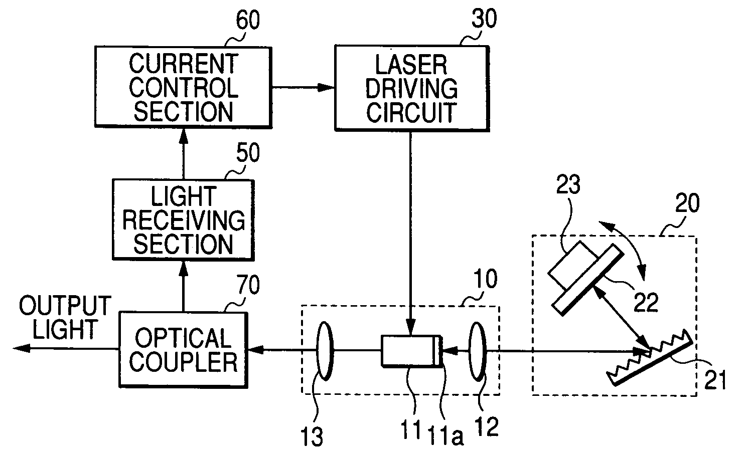
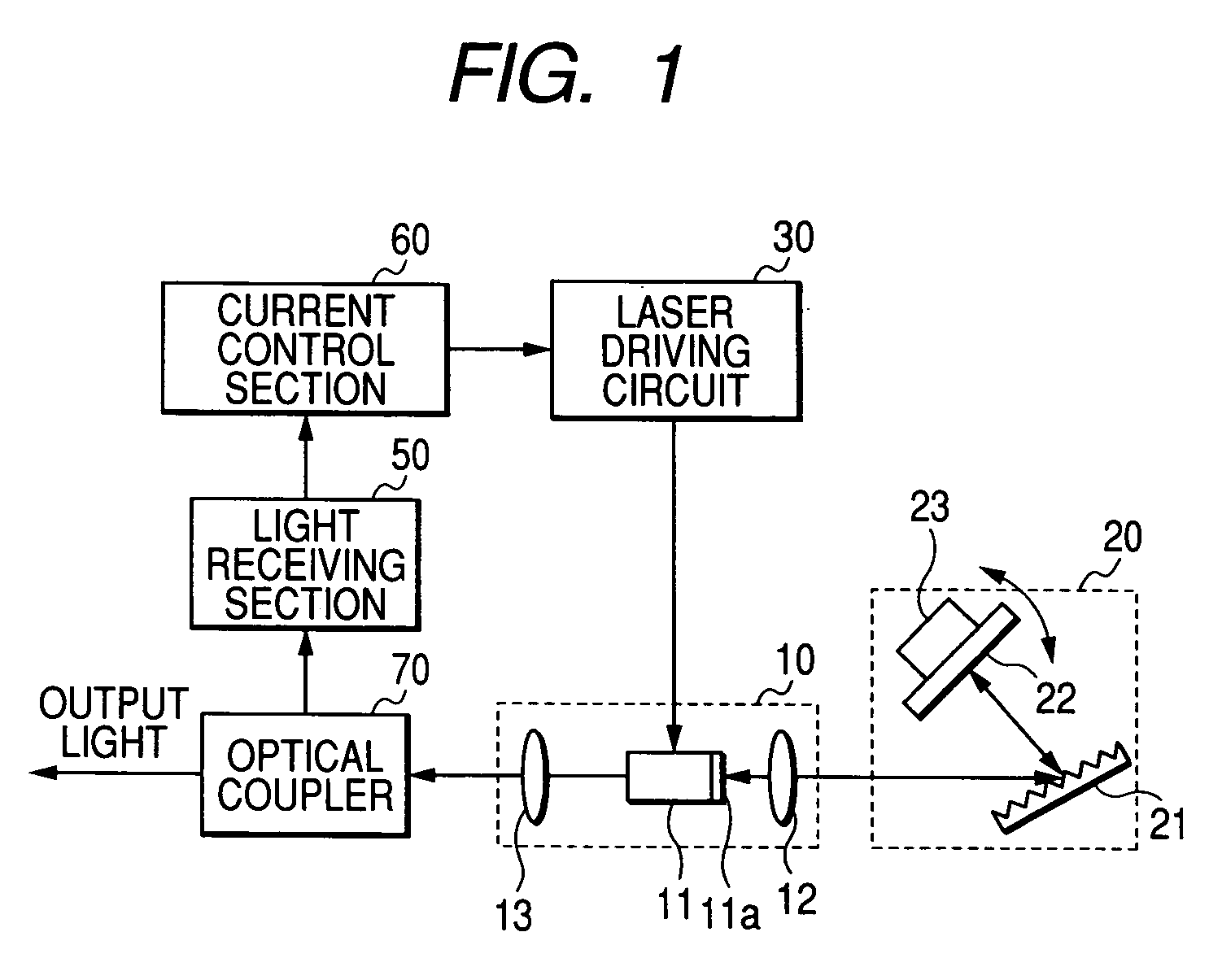
[0038]FIG. 1 is a diagram showing the configuration of a first embodiment of the invention. The components which are identical with those of FIG. 4 are denoted by the same reference numerals, and their description is omitted. Referring to FIG. 1, an optical coupler 70 is provided in place of the optical coupler 40 in FIG. 4. The optical coupler 70 is branches the laser light that is input from the semiconductor laser 11 via the second lens 13. The optical coupler 70 outputs one branched light as output light of the tunable laser source, and supplies the other branched light to the light receiving section 50.

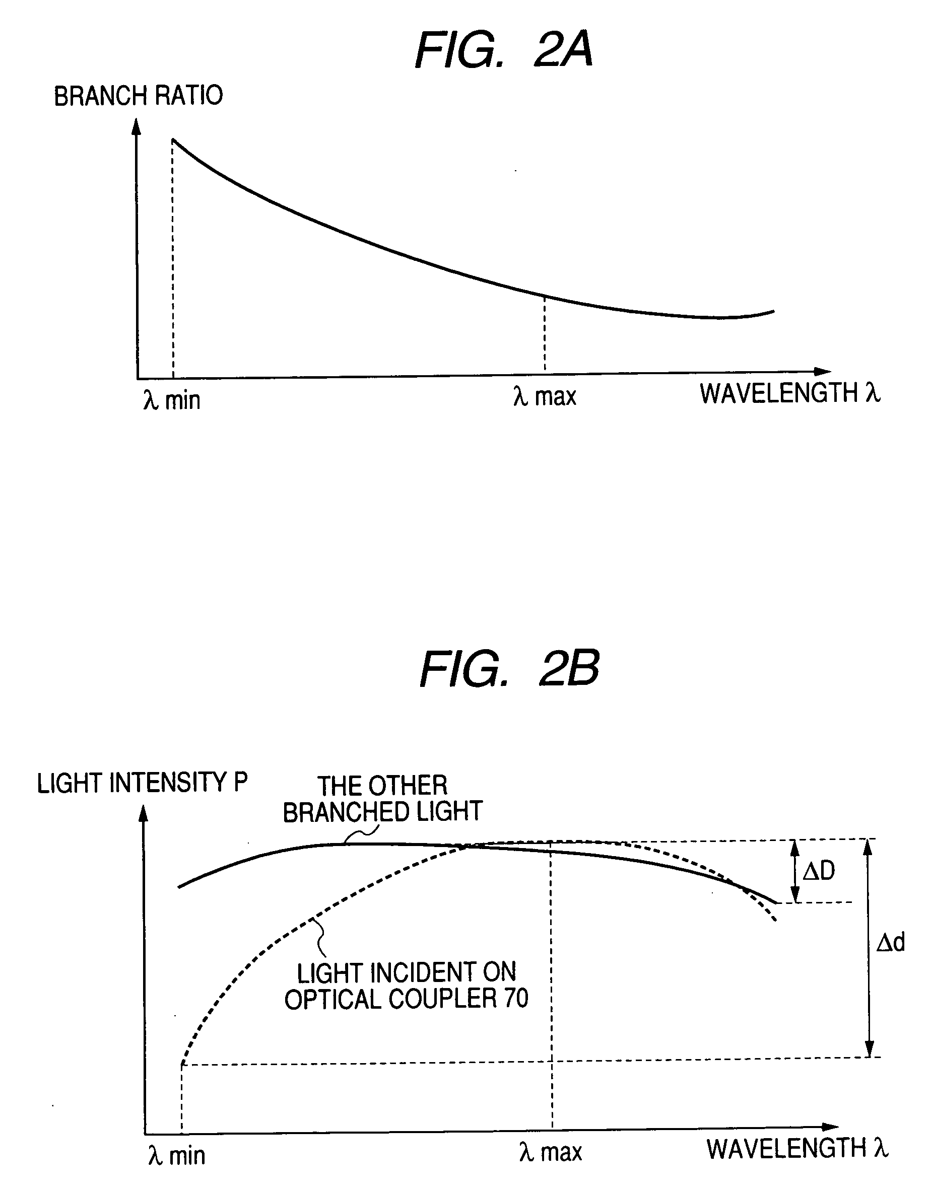
[0039] The branch ratio of the optical coupler 70 is not constant in a predetermined wavelength range, i.e., the tunable range, and has wavelength characteristics which have a substantially inverted shape with respect to the wavelength characteristics of the light intensity of the laser light of the semiconductor laser 11. In the wavelength characteristics of th...

Example

Second Embodiment

[0046] In the light source shown in FIG. 1, the configuration in which the intensity of the output light is adjusted by controlling the laser driving current of the semiconductor laser 11 has been described. Alternatively, the intensity of the output light is adjusted by attenuating the intensity of the laser light emitted from the semiconductor laser 11 (For example, see JP-A-2002-232075.). FIG. 3 is a diagram showing the configuration of a second embodiment of the invention. The components which are identical with those of FIG. 1 are denoted by the same reference numerals, and their description is omitted. Referring to FIG. 3, an optical attenuator 80 is disposed between the second lens and the optical coupler 70. In place of the current control section 60, an attenuation control section 90 is provided.

[0047] In accordance with instructions from the attenuation control section 90, the optical attenuator 80 attenuates the laser light emitted from the semiconducto...


PUM


Abstract

A tunable laser source has a semiconductor laser which outputs laser light over a predetermined wavelength range, a laser driving circuit which supplies a laser driving current to the semiconductor laser, a light receiving section which receives the laser light output from the semiconductor laser, a current control section which controls the laser driving current output from the laser driving circuit based on a light intensity of the laser light received by the light receiving section, and a branch section which branches the laser light output from the semiconductor laser to output one branched light as output light and output another branched light to the light receiving section. The branch section has wavelength characteristics of a branch ratio in the predetermined wavelength range where a light intensity ratio of the another branched light is smaller than a light intensity ratio of the laser light output from the semiconductor laser.

Description

CROSS-REFERENCE TO RELATED APPLICATIONS [0001] This application is based upon and claims the benefit of priority from the prior Japanese Patent Applications No. 2004-271407, filed on Sep. 17, 2004, the entire contents of which are incorporated herein by reference. BACKGROUND OF THE INVENTION [0002] 1. Field of the Invention [0003] The invention relates to a tunable laser source which is useful in optical communications, a measuring device for the optical communication, the other optical measuring devices, and which can vary the wavelength over a wide range. The invention particularly relates to a tunable laser source in which the light intensity of output light can be accurately adjusted. [0004] 2. Description of the Related Art [0005] An external resonator type tunable laser source can vary the wavelength of output light over a wide range. Laser light of a semiconductor laser is monitored so that the light intensity of output light (also called the optical power) is a preset light ...

Claims


Application Information

Patent Timeline
IPC IPC(8): H01S3/10
CPCH01S5/0683H01S5/143H01S5/141
Inventor KUBOTA, HIROSHI
Owner YOKOGAWA ELECTRIC CORP
Why Eureka
Try Eureka