
Temperature compensated lasers

a laser and temperature compensation technology, applied in semiconductor lasers, laser cooling arrangements, laser details, etc., can solve the problems of reducing the decay of slope efficiency with temperature, using to its maximum practical limit, and not having an effective method of controlling temperature variation of slope efficiency d/d

Inactive Publication Date: 2006-03-23
LUMENTUM OPERATIONS LLC
View PDF9 Cites 13 Cited by
  • Summary
  • Abstract
  • Description
  • Claims
  • Application Information

AI Technical Summary

Benefits of technology

The present invention provides a method and device for controlling the temperature variation of a semiconductor laser. The invention includes a semiconductor laser with at least one mirror that has varying reflectivity or transmissivity at different temperatures. This allows for compensation of the laser for temperature variations and ensures stable output power. The invention also provides optical means for compensating the semiconductor laser for temperature variations in the slope of output power vs. input power. The technical effects of the invention include improved temperature stability and stable output power of the semiconductor laser.

Problems solved by technology

In prior art devices, there has been no effective method for controlling temperature variation of the slope efficiency dη / dT.
This approach is generally already used to its maximum practical limit.
It only reduces the decay of slope efficiency with temperature, but its effect is limited by the availability of material structures that are consistent with the desired laser emission wavelength.
Furthermore, optimizing for quantum mechanical confinement may involve compromises with other aspects of the laser such as electrical resistance or manufacturability.

Method used


Image

  • Temperature compensated lasers
  • Temperature compensated lasers
  • Temperature compensated lasers

Examples


example 1

EXAMPLE 1

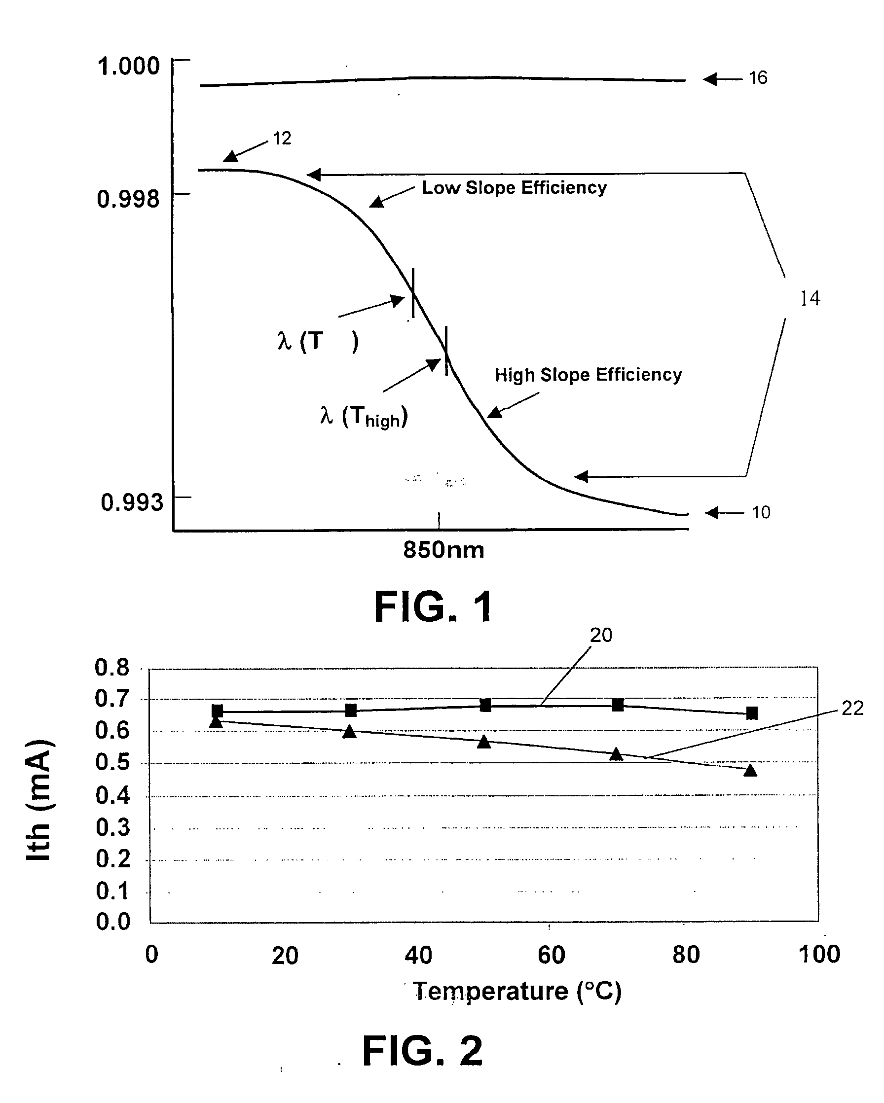
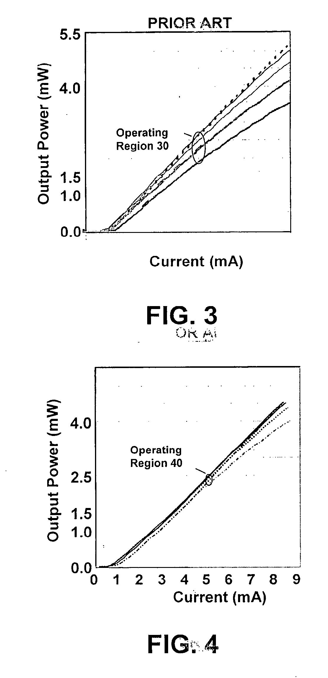
[0072] Experiments were conducted on experimental VCSELs. In experimental VCSELs, if the temperature was raised from 10° C. to 70° C., the slope efficiency at the higher temperature is less than 80% of the slope at the lower temperature. In a first experiment using a slight modification of the VCSEL top mirror as described above, the magnitude of dη / dT was experimentally reduced to less than ½; the slope efficiency at 70° C. was greater than 91% of the 10° C. value. Further reductions in dη / dT were made by making more changes to the top mirror.

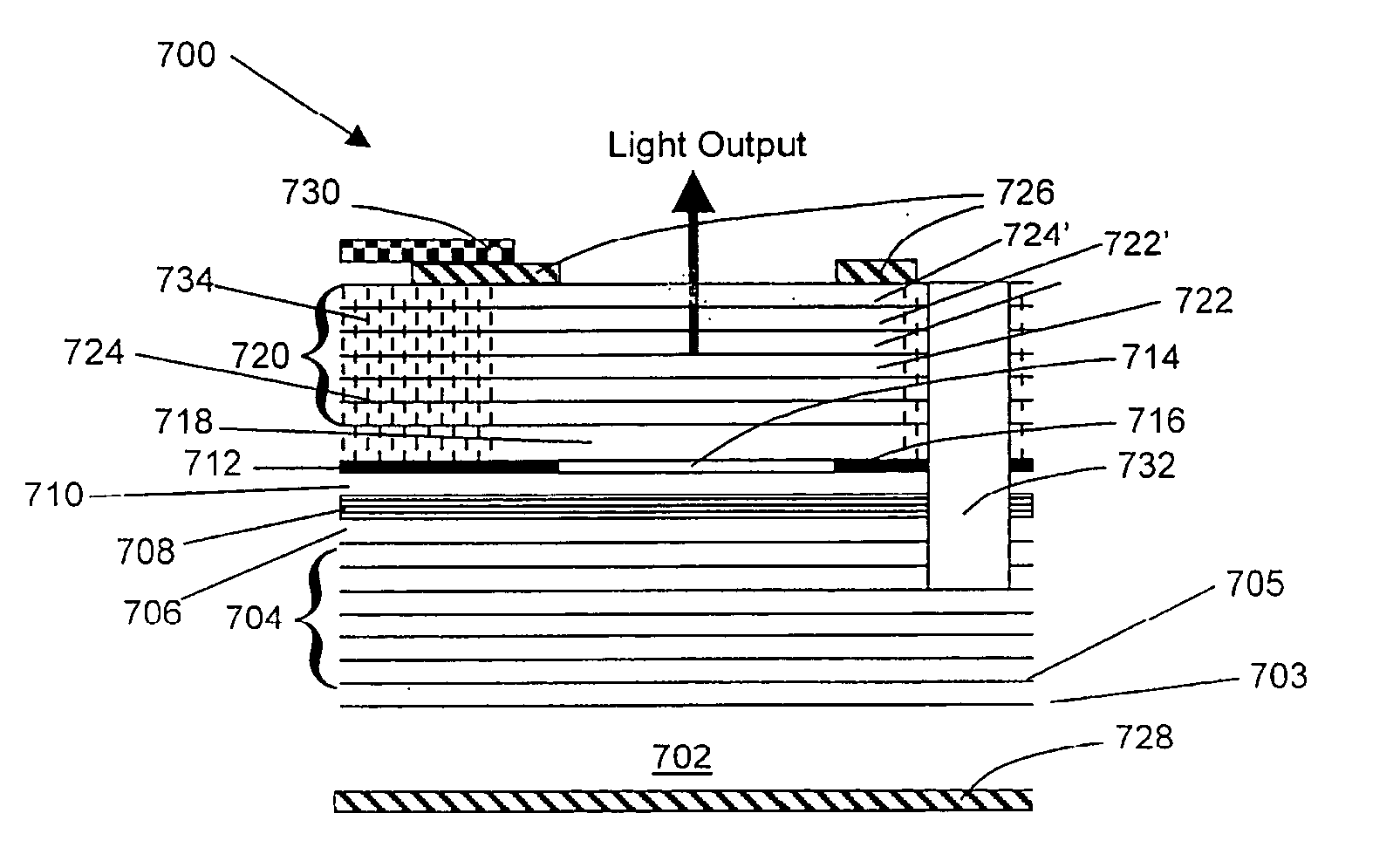
[0073] The experimental reduction in dη / dT was achieved by using a top-emitting VCSEL whose top mirror reflectivity decreased with increasing wavelength, see FIGS. 1, 8 and 10A. Since the wavelength of a semiconductor laser increases with temperature, the increased wavelength resulted in a lower reflectivity of the mirror. The lower reflectivity produced a relative increase in η, which largely compensated for the quantum-mechanically...


PUM


Abstract

A novel approach for providing temperature compensation for semiconductor lasers is disclosed. This approach utilizes reflectivity characteristics in the at least one of the mirrors of the semiconductor laser to provide temperature compensation to the device.

Description

CROSS-REFERENCE TO RELATED APPLICATIONS [0001] This application makes-reference to the following co-pending U.S. patent applications. The first application is U.S. application Ser. No. 08 / 699,697, entitled “Extended Wavelength Strained Layer Lasers Having Short Period Superlattices,” filed Sep. 26, 1996. The second application is U.S. application Ser. No. 08 / 721,589, entitled “Extended Wavelength Strained Layer Lasers Having Strain Compensated Layers,” filed Sep. 26, 1996. The third application is U.S. application Ser. No. 08 / 721,590, entitled “Extended Wavelength Strained Layer Lasers Having Nitrogen Disposed Therein,” filed Sep. 26, 1996. The fourth application is U.S. application Ser. No. 08 / 574,165, entitled “Conductive element with Lateral Oxidation Barrier,” filed Dec. 18, 1995. These applications are hereby incorporated by reference.[0002] This invention is made with government support under contract number DASG60-98-C-0032, awarded by the US Army Space and Missile Defense Co...

Claims


Application Information

Patent Timeline
Patent Type & Authority Applications(United States)
IPC IPC(8): H01S5/00H01S5/028H01S5/068H01S5/183
CPCH01S5/02461H01S5/0284H01S5/0612H01S5/06804H01S5/1221H01S5/3095H01S5/18341H01S5/18358H01S5/18369H01S5/18377H01S5/18311H01S5/18322
Inventor JEWELL, JACK L.
Owner LUMENTUM OPERATIONS LLC
Learn More