Antireflective film and optical element

an anti-reflection film and optical element technology, applied in the field of anti-reflection films and optical elements, can solve the problems of difficult in some cases to sufficiently satisfy optical performance, uneven variation rate of surface angle or curvature of optical surfaces, etc., and achieve the effect of reducing ghost effect and small variation in optical properties

Inactive Publication Date: 2013-08-08
HOYA CORP
View PDF1 Cites 10 Cited by
  • Summary
  • Abstract
  • Description
  • Claims
  • Application Information

AI Technical Summary

Benefits of technology

[0035]According to the present invention, the antireflection film of a smaller number of layers can be formed, and therefore variation in optical properties is small over the whole body of the antireflection film, and the ghost can be effectively reduced.

Problems solved by technology

Meanwhile, in a case of a concave meniscus lens with the optical surface formed into an aspherical surface, a variation rate of a surface angle or the curvature of the optical surface is not formed uniformly.
However, in recent years, it is difficult in some cases to sufficiently satisfy an optical performance requested in an optical system only by uniformly suppressing the reflectance to be low in the visible light region.

Method used


Image

  • Antireflective film and optical element
  • Antireflective film and optical element
  • Antireflective film and optical element

Examples


modified example 1

of the First Example

[0109]As a modified example 1 of the above-mentioned example, FIG. 6 shows a film structure of the three-layer antireflection film formed by performing film formation of the first layer and the second layer twice, and the method of forming this antireflection film will be described hereafter. By forming a relatively thick film by performing film formation twice, uniformity of a film quality (such as refractive index and film density, etc.) in a film thickness direction can be improved, and controllability of the film thickness during deposition can be improved. Therefore, a film having a desired film design value (optical film thickness) can be stably formed.

The first layer: forming condition of the Al2O3 film

The film formation of the first layer is performed twice, to thereby equalize the film structure.

(First Film Formation)

[0110]Substrate heating: about 260° C.[0111]Vacuum degree during film formation after introducing oxygen: 7.2×10⁻³ Pa[0112]Deposition rate:...

modified example 2

of the First Example

[0126]In addition, as a modified example 2 of the first example, FIG. 8 shows the film structure of the three-layer antireflection film formed by performing film formation of the first layer and the second layer of the first example twice, while providing a difference in the film structure between the first film formation and the second film formation, and performing a fine adjustment of the optical property. The method of forming this antireflection film is described hereafter. In the modified example 2, the film formation is performed by performing film formation of the first layer and the second layer twice, while providing a difference in the film structure between the first layer and the second layer. The difference is provided in the film structure because in the same constitutional material, when the film quality is varied in a film thickness direction, such a variation in the film quality in the film thickness direction can be canceled by providing the di...

second example

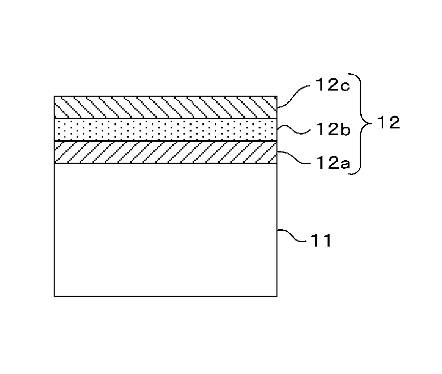
[0144]FIG. 10 shows a specific second example of the antireflection film (four-layer film structure: Sub / x1L / x2M / yH / zL / Air). First, the constitutional material is as follows: the optical glass by HOYA Corporation (glass type: M-BACD12) is used for the base material of the concave meniscus lens 11. Further, In each layer constituting the antireflection film, the first layer 12a is made of aluminum oxide (Al2O3), and the second layer 12b is made of aluminum oxide (Al2O3), and the third layer 12c is made of an optical film material by Canon optron Inc., (product name: OH-5 (a mixed film of zirconium and titanium oxide (ZrO2+TiO2)), and a fourth layer 12d is made of magnesium fluoride (MgF2). Further, the ratio of a mixed material constituting the third layer is ZrO2:TiO2=9:1. The following numerical range can be applied to the numerical values of x, y, z.

x1=0.01 to 0.50

x2=1.00 to 1.60

y=0.70 to 2.30

z=0.70 to 1.30

[0145]The film structure of each layer is shown in FIG. 10.

(The Method of M...


PUM

PropertyMeasurementUnit
incident angleaaaaaaaaaa
refractive indexaaaaaaaaaa

Abstract

An antireflection film including an optical element, formed on an optical surface of an optical member, and is configured to prevent a reflection of a light beam incident on the optical surface, wherein a maximum reflectance P1 in a first wavelength region and a maximum reflectance P2 in a second wavelength region at a wavelength side longer than the first wavelength region, satisfies a relation of P1>P2, as a spectral reflectance property when a light beam is incident on the optical surface at an incident angle of 0 degree; and by shifting a wavelength range where the reflectance is a specific value or less, to a wavelength side longer than the second wavelength region, the reflectance in the second wavelength region is decreased, and the reflectance in the first wavelength region is increased so that a luminance difference is small between a ghost in the first wavelength region and a ghost in the second wavelength region.

Description

BACKGROUND[0001]1. Technical Field[0002]The present invention relates to an antireflection film and an optical element including the antireflection film.[0003]2. Description of Related Art[0004]An antireflection film is provided on a surface of a lens or a cover glass used in a photographic camera (including a digital camera), a broadcast camera, a monitoring camera installed on a vehicle or outdoor, and an astronomical telescope, etc., for suppressing a loss of a transmitted light, or preventing a ghost or flare. The antireflection film having a following film structure is proposed: the antireflection film is designed so that a low refractive index film and a high refractive index film are laminated, and a reflected light generated on an interface between each layer, and a light beam incident on each layer are canceled each other by interference.[0005]For example, patent document 1 discloses an antireflection film composed of four layers having a reflectance of 0.5% when an inciden...

Claims


Application Information

Patent Timeline
Patent Type & Authority Applications(United States)
IPC IPC(8): G02B1/11G02B1/115
CPCG02B1/11G02B27/0018G02B3/04G02B1/115
Inventor KAWAGISHI, SHUICHIROYAMASHITA, TERUO
Owner HOYA CORP
Why Eureka
Try Eureka