Method to assemble marine drive system, and marine propulsion apparatus

a drive system and marine technology, applied in marine propulsion, vessel parts, vessel construction, etc., can solve the problems of system disassembly and replacement of parts causing problems, and achieve the effect of improving gear sound

Inactive Publication Date: 2006-03-23
YANMAR POWER TECHNOLOGY CO LTD
View PDF11 Cites 6 Cited by
  • Summary
  • Abstract
  • Description
  • Claims
  • Application Information

AI Technical Summary

Benefits of technology

[0027]“Components constituting a shafting” in the present specification include a propeller shaft, a propeller, a elastic coupling, an additional mass and like peripher...

Problems solved by technology

Therefore, in prior art techniques, a test working is given after the completion of assembling, and if the torsional vibration of the marine drive system and rat...

Method used


Image

  • Method to assemble marine drive system, and marine propulsion apparatus
  • Method to assemble marine drive system, and marine propulsion apparatus
  • Method to assemble marine drive system, and marine propulsion apparatus

Examples


Embodiment Construction

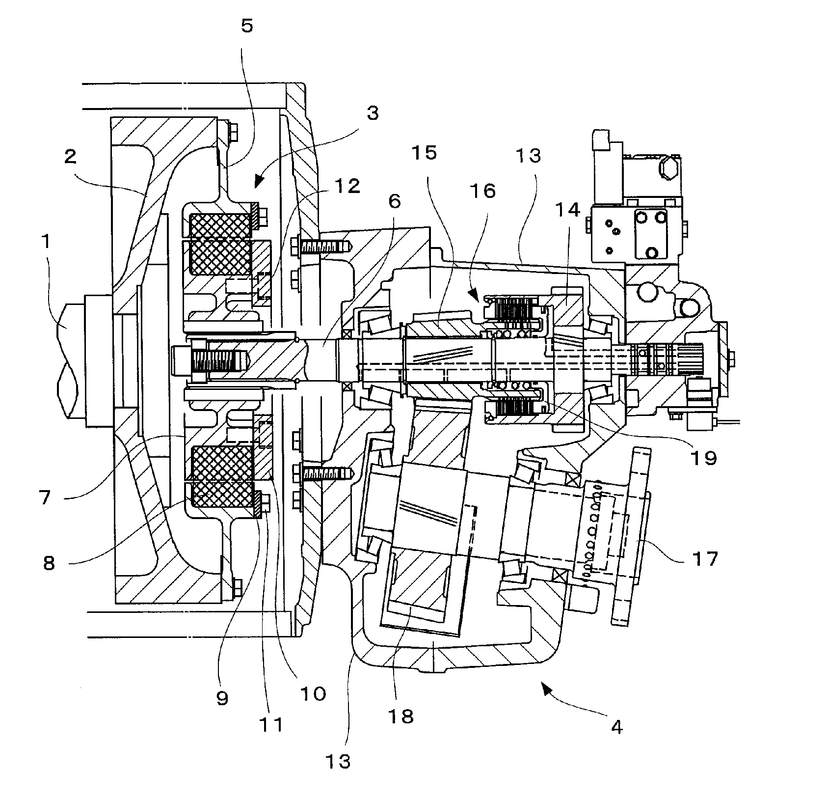
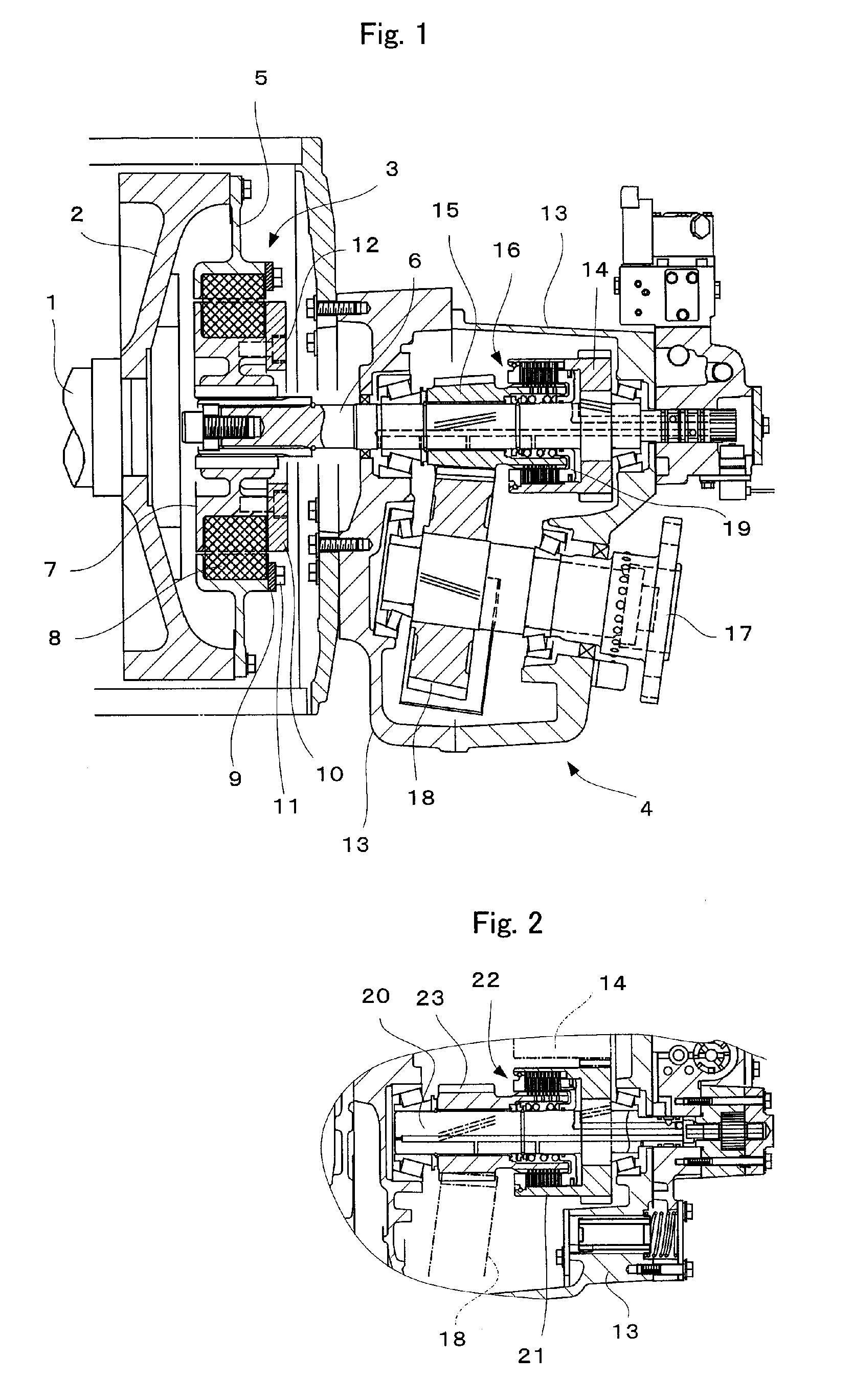
[0038] Embodiments of the method to assemble a marine drive system of the present invention will be explained below with reference to FIGS. 1 to 10. In the figures, the same reference numbers are used for the same constituent components. The marine drive system comprises a drive shaft 1 connected to an engine (not shown), a flywheel 2 fixed to the drive shaft 1, an elastic coupling 3, and a marine reverse and reduction gear 4. In the figures, the propeller shaft and propeller are omitted.

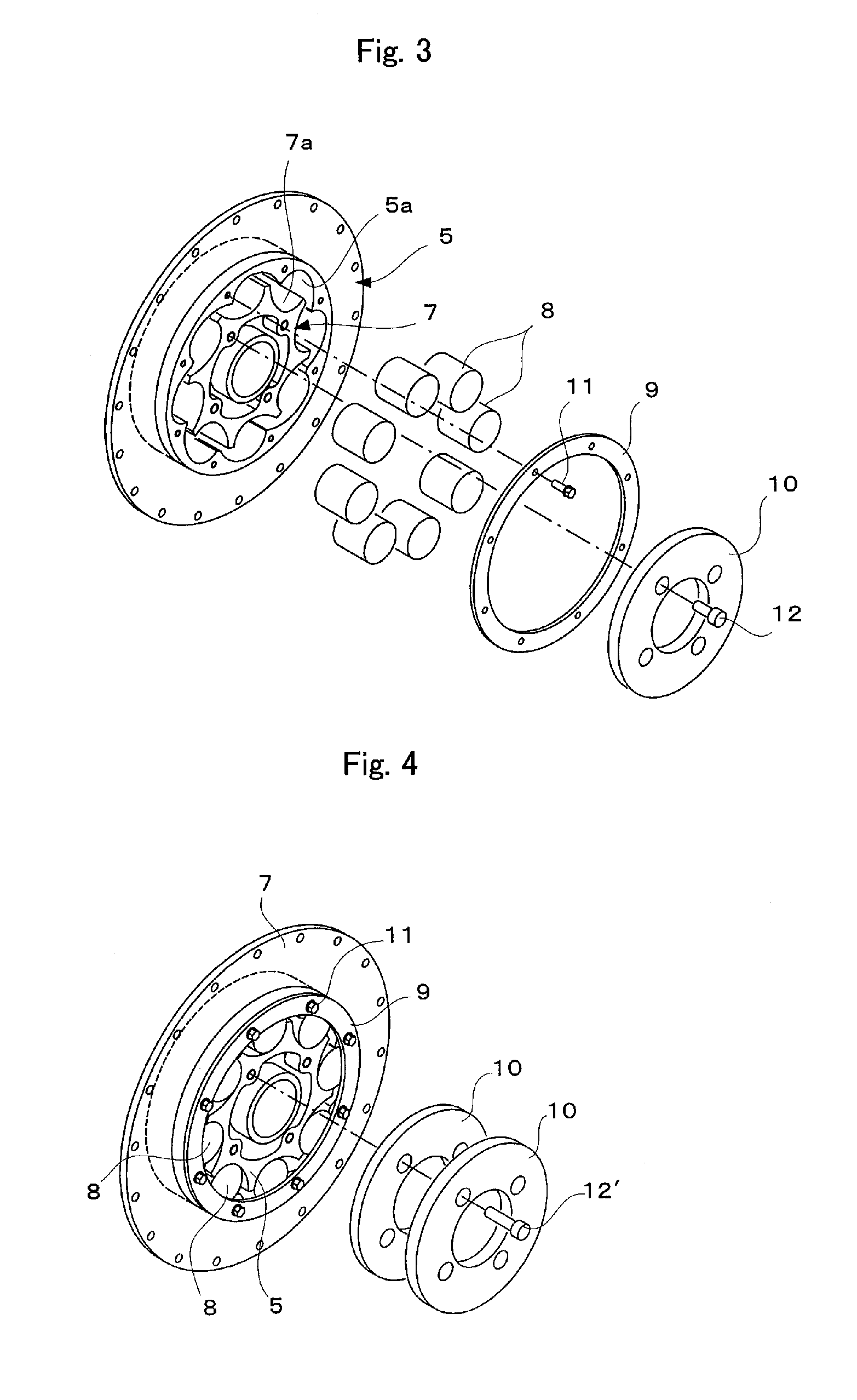
[0039] As shown in FIGS. 1, 3 and 4, the elastic coupling 3 comprises an outer ring 5 fixed to the flywheel 2, an inner ring 7 engaged with splines to the input shaft 6 of the marine reverse and reduction gear 4, and a plurality of elastic blocks 8 held between the outer ring 5 and the inner ring 7. An opposing plurality of concave portions 5a and 7a are formed on the inner surface of the outer ring 5 and the outer surface of the inner ring 7, and the elastic blocks 8 are detachably placed in such ...


PUM


Abstract

The present invention provides a method to assemble a marine drive system wherein an acceptable-unacceptable criterion on the torsional vibration of a shaft of the marine drive system is established based on the correlation between the torsional stiffness of a propeller shaft and the moment of inertia of a propeller; a desirable component for the marine drive shaft is selected based on the criterion; and the marine drive system is assembled by using the selected components, the marine drive system comprising a flywheel 2, a marine reverse and reduction gear 4, and a elastic coupling 3, whose property are changeable, lying between an input shaft of the marine reverse and reduction gear 6 and the flywheel 2; and the component for the shaft of the marine drive system is the elastic coupling.

Description

TECHNICAL FIELD [0001] The present invention relates to a method to assemble a marine drive system that transmits engine power, and to a marine propulsion apparatus. BACKGROUND ART [0002] Marine reverse and reduction gears usually comprise an input shaft, output shaft, and friction clutch between the input and output shafts. The input shaft is connected to a flywheel coupled to a drive shaft of the engine via an elastic coupling (for example, those disclosed in Japanese Unexamined Patent Publication No. 1995-35150 and Specification of U.S. Pat. No. 6,244,964), and the output shaft is connected to a propeller shaft. The output from the engine is transmitted to the propeller shaft via the drive shaft, flywheel, coupling and marine reverse and reduction gear. A marine drive system is composed of these components (for example, Specification of U.S. Pat. No. 4,679,673). [0003] Each component of such a marine drive system is produced by a manufacturer specializing in the field (for exampl...

Claims


Application Information

Patent Timeline
IPC IPC(8): B63H23/34
CPCB63H21/30B63H23/08B63H21/305
Inventor NAKAGAWA, SHIGEAKIIMANAKA, TOSHIO
Owner YANMAR POWER TECHNOLOGY CO LTD
Why Eureka
Try Eureka