Method of making a textile material and textile material made thereby

Inactive Publication Date: 2006-03-23
NANGLA KIREN
View PDF2 Cites 0 Cited by
  • Summary
  • Abstract
  • Description
  • Claims
  • Application Information

AI Technical Summary

Benefits of technology

[0020] Preferably the stretching of the fabric should be sufficient to propagate stitch rupture or breaking. The rupture of stitches will cause the fabric to “ladder”. The rupture of stitches typically occurs in the weft direction of the fabric and the laddering effect typically occurs longitudinally of the fabric. The stitch rupturing or laddering is typically as a r

Problems solved by technology

As such, conventional textile ma

Method used


Image

  • Method of making a textile material and textile material made thereby

Examples


Example

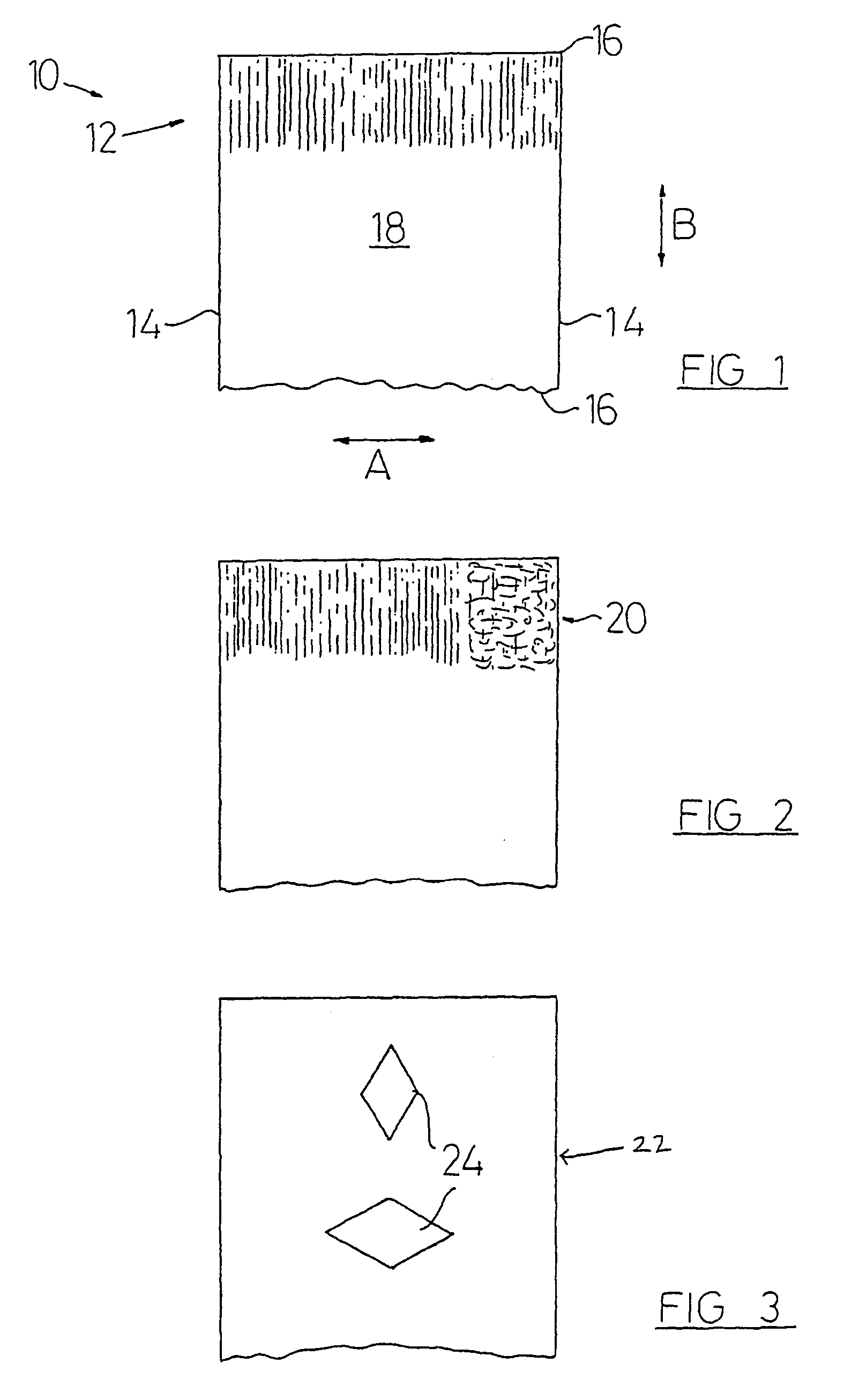
[0030] The method according to the present invention employs the steps of choosing a warp-knitted, weft knitted or woven base fabric. In this example, the fabric is a weft-knitted fabric (one by one rub knit) made of texturised polyester and is of 28 gauge. The weft fabric includes a single yarn with interlocking loops which builds up the fabric. The threads running across the fabric are called “causes” or “warp”. The threads running longitudinally of the fabric are called “wales” or “weft”.

[0031] A coating is applied to the fabric using the “Metatran”™ foil transfer system. This system utilises a screen printable adhesive and a heat transfer foil, and is used for the production of mirror-finished metallic prints commonly referred to as metallic lame fabrics. There are two procedures of making a textile material using the Metatran system.

[0032] The first procedure is to apply or print the adhesive directly onto the fabric. The adhesive is then set, for example in a convection oven...


PUM

PropertyMeasurementUnit
Lengthaaaaaaaaaa
Fractionaaaaaaaaaa
Stretching forceaaaaaaaaaa

Abstract

A textile material is provided, the appearance of which can be changed by stretching a whole or a part of the material in one or more pre-determined directions. The textile material is formed using a base fabric onto which one or more coating layers (e.g. metallic coating) are applied. The coated fabric is then stretched in a substantially transverse direction to the fabric and then in a substantially longitudinal direction to the fabric.

Description

FIELD OF THE INVENTION [0001] This invention relates to a method of making a textile material, and to a textile material made thereby. BACKGROUND TO THE INVENTION [0002] Many types of textile materials are known and such materials can be formed for example, by weaving threads together to form a woven textile material or by knitting threads together to form a knitted textile material. Knitted fabrics or material are typically referred to as weft-knitted fabrics in which the threads follow a path generally transversely or across the width of the fabric, or warp-knitted fabrics in which a number of warp threads follow a path which is generally longitudinal or along the length of the fabric. However, knitted and woven fabrics include warp and weft threads therein. [0003] Further examples of known textile materials include those which are made up of threads which exhibit different colours when viewed from differing angles, so that a textile can appear blue when viewed from one angle, and...

Claims


Application Information

Patent Timeline
IPC IPC(8): B32B27/04B32B5/08B32B15/14B32B5/26A41D31/00B32B15/04D03D15/56D06C3/00D06M11/83D06Q1/00D06Q1/04D06Q1/08
CPCA41D31/00D06C3/00D06Q1/08D06Q1/04D06Q1/00Y10T442/20Y10T442/3415Y10T442/475Y10T442/3382Y10T442/3301Y10T442/3008Y10T442/40Y10T442/3602Y10T442/2738
Inventor NANGLA, KIREN
Owner NANGLA KIREN
Why Eureka
Try Eureka