Method for correcting hyperopia and presbyopia using a laser and an inlay outside the visual axis of eye

Inactive Publication Date: 2006-03-23
MINU
View PDF6 Cites 56 Cited by
  • Summary
  • Abstract
  • Description
  • Claims
  • Application Information

AI Technical Summary

Benefits of technology

[0011] Yet another object of the present invention is to provide a method for resphaping a

Problems solved by technology

Ametropia is the inability of the lens and cornea to focus the far point correctly on the retina.
Presbyopia is an age related condition, and it is general

Method used


Image

  • Method for correcting hyperopia and presbyopia using a laser and an inlay outside the visual axis of eye
  • Method for correcting hyperopia and presbyopia using a laser and an inlay outside the visual axis of eye
  • Method for correcting hyperopia and presbyopia using a laser and an inlay outside the visual axis of eye

Examples


first embodiment

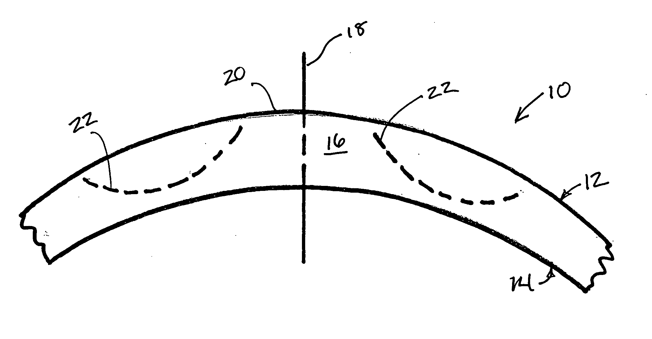
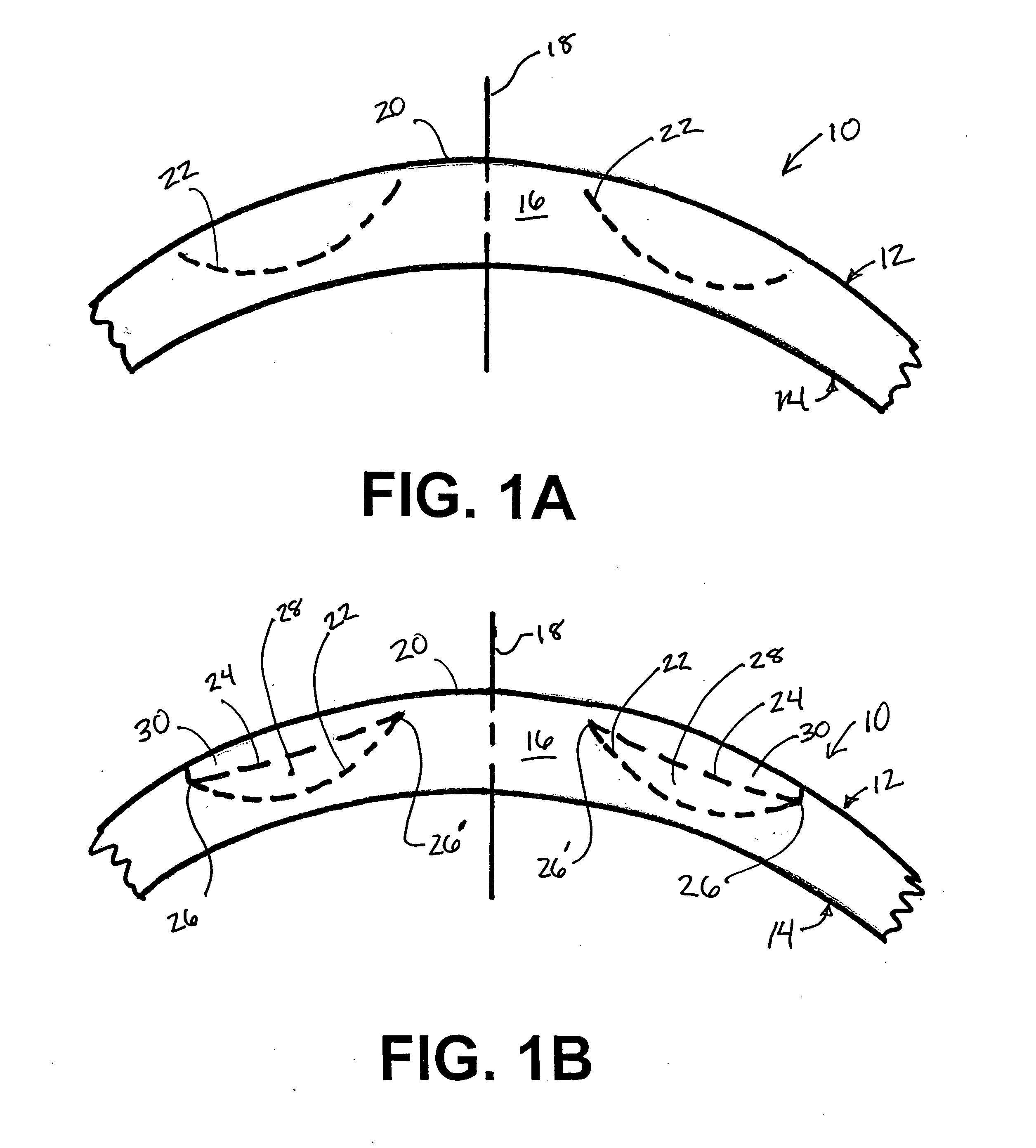
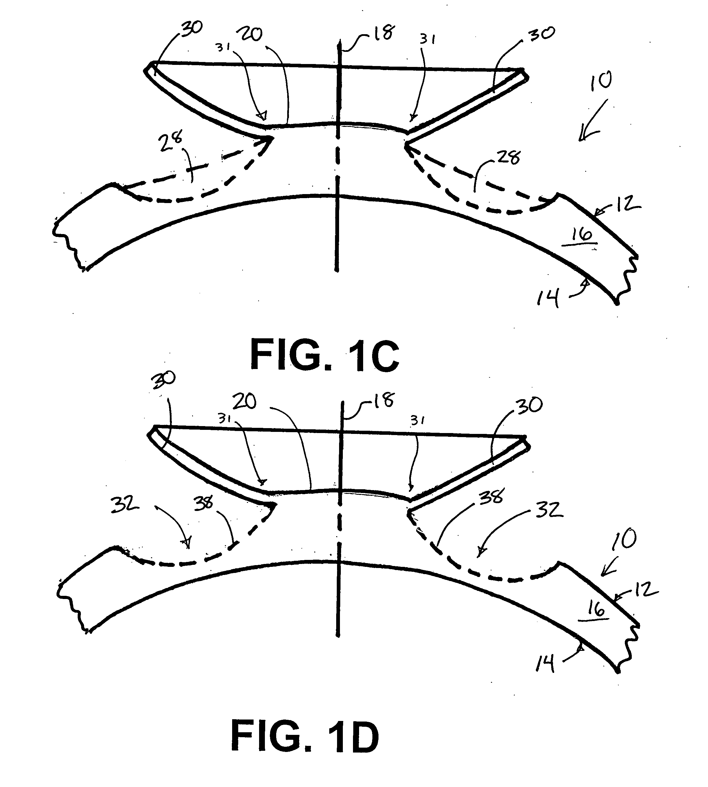
[0042]FIGS. 1A-1I illustrate a method of correcting hyperopic or presbyopic errors in an eye according to the present invention. As seen in those figures, the cornea 10 has an epithelium 12 (the external, exposed layer of the cornea), an endothelium 14 (the internal layer of the cornea), and a stroma 16 located therebetween. The cornea 10 has a central visual or optical axis 18 which passes through the central area 20 of the cornea 10.

[0043] To correct for hyperopia or presbyopia, the refractive power of the cornea 10 must be increased. In the method of the present invention, this is accomplished by reshaping the cornea 10. As seen in FIG. 1A, a first curvilinear cut 22 is created in the stroma 16 using an ultra-short pulse laser, such as a femtosecond laser. The use of an ultra-short pulse laser is desirable because such a laser creates precise intrastromal cuts with little corneal trauma. A suitable ultra-short pulse laser is the IntraLase FS laser available from the IntraLase Cor...

embodiment

of FIG. 11

[0051]FIG. 11 illustrates a third embodiment of the present invention. In this embodiment, an ultra-short pulse laser makes a first cut 90 through the epithelium 92 of the cornea 94 to create a corneal flap 96. The laser is then used to soften a portion 98 of the cornea by selectively aiming and firing the laser at a portion of the stroma 100 located below the corneal flap 96. The corneal flap 96 can then be lifted, and the softened portion 98 of the stroma 100 can be removed using a spatula or any other suitable instrument. After the softened portion has been removed, the remainder of the treatment takes place as discussed above with respect to the first embodiment.

Embodiment of FIGS. 12-14

[0052]FIGS. 12-14 illustrate a fourth embodiment of the present invention. In this embodiment, a corneal flap 102 is formed and raised to form an exposed portion 106 of the stroma 104. A drill bit 108 is then used to remove a portion of the stroma 104. Once the desired amount of stroma...


PUM


Abstract

A cornea is reshaped by first creating a first cut in the cornea using an ultra-short pulse laser. The first cut is located below the surface of the cornea and does not extend through the epithelium. A second cut is then created using the ultra-short pulse laser. The second cut creates a corneal flap and intersects with the first cut to create a substantially severed portion of the cornea located between the first cut and the second cut. The severed portion of the cornea is located outside of the visual axis of the eye. The corneal flap is lifted away from the severed portion, and the severed portion is removed from the eye. The corneal flap is moved into the space on the cornea previously occupied by the severed portion. The cornea is thereby reshaped, and the reshaped portion of the cornea has an increased refractive power, correcting for hyperopic and presbyopic conditions.

Description

FIELD OF THE INVENTION [0001] The present invention generally relates to the correction of refractive errors in an eye. More specifically, the present invention relates to a method of correcting refractive errors in an eye by reshaping the cornea to provide increased refractive power for near vision. BACKGROUND OF THE INVENTION [0002] A normal emetropic eye includes a cornea, a lens, and a retina. The cornea and lens cooperatively focus light entering the eye from a far point—i.e. infinity—onto the retina. An eye can have a disorder known as ametropia, however. Ametropia is the inability of the lens and cornea to focus the far point correctly on the retina. Typical types of ametropia are myopia, hypermetropia or hyperopia, and astigmatism. [0003] A hypermetropic or hyperopic eye has an axial length shorter than that of a normal emetropic eye, or a lens or cornea with a refractive power less than that of a lens and cornea of an emetropic eye. This lesser refractive power causes light...

Claims


Application Information

Patent Timeline
IPC IPC(8): A61F9/008
CPCA61F9/008A61F9/00827A61F2009/00895A61F9/00838A61F2009/00872A61F9/00834
Inventor PEYMAN, GHOLAM A.
Owner MINU
Why Eureka
Try Eureka