Generating scanning spot locations for laser eye surgery

a laser eye surgery and laser beam technology, applied in the field of tissue removal techniques, can solve the problems of large processing time, small spot scanners with their problems, and high processing costs, and achieve the effect of simplifying overlap analysis

Inactive Publication Date: 2006-03-07
AMO MFG USA INC
View PDF13 Cites 28 Cited by
  • Summary
  • Abstract
  • Description
  • Claims
  • Application Information

AI Technical Summary

Benefits of technology

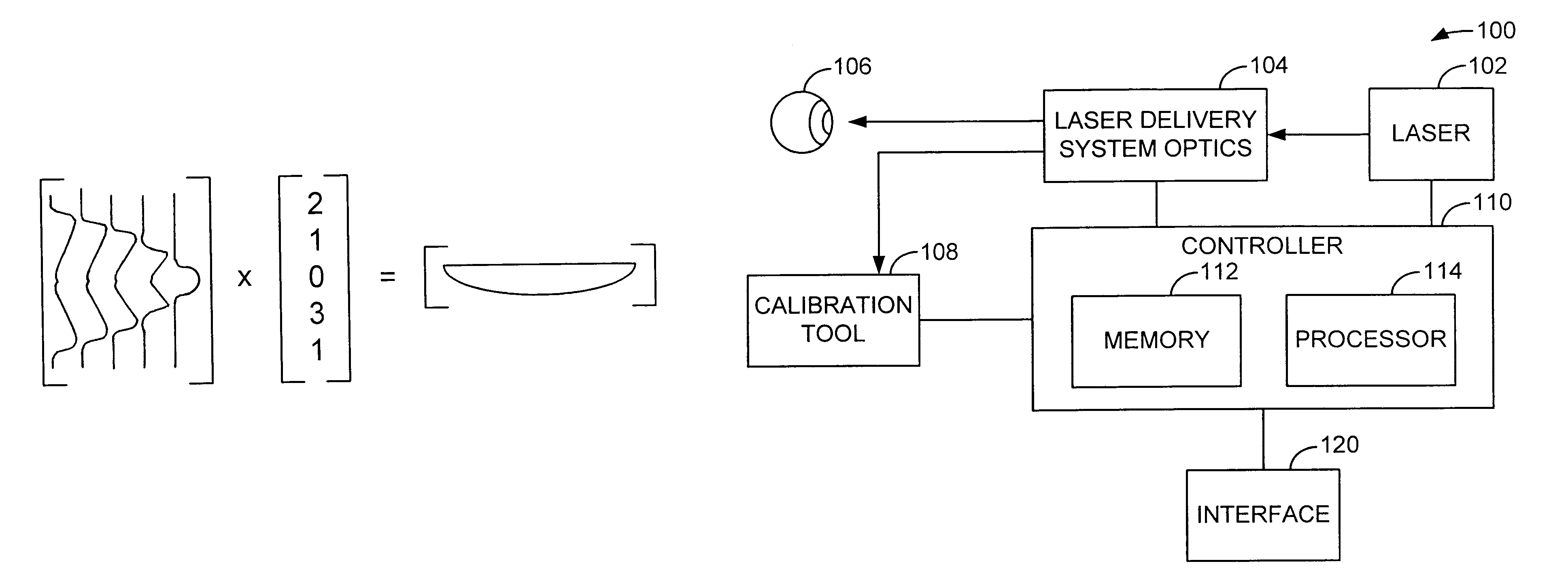
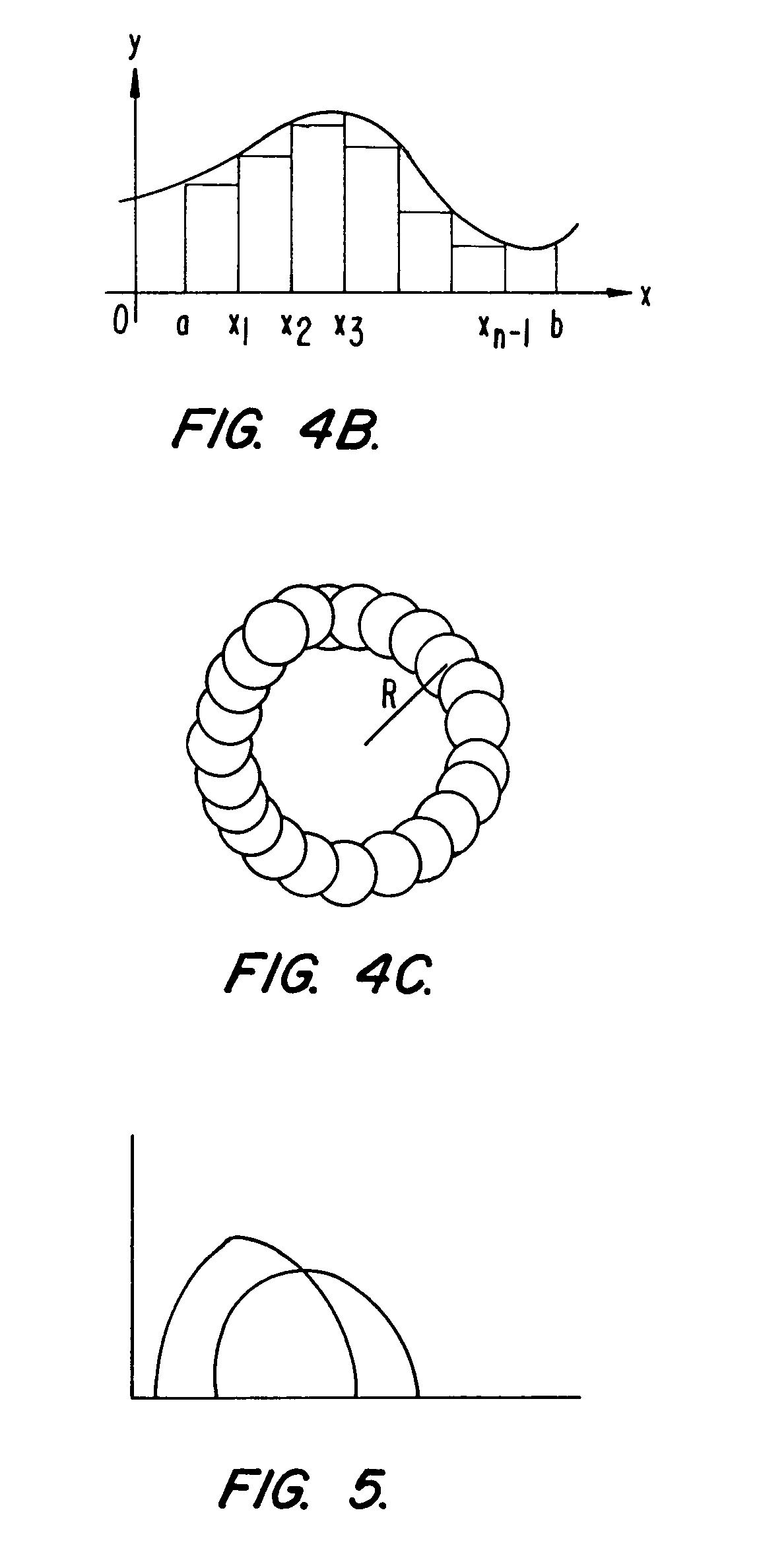
[0006]The present invention relates to tissue ablation utilized in, for instance, corneal sculpting. In general, embodiments of the invention determine a treatment table containing scanning spot locations and characteristics (e.g., size, shape, and depth) for directing overlapping scanning spots of a laser beam to achieve a target ablation profile. Some embodiments of the invention use symmetry effects (e.g., axisymmetry or bilateral symmetry) to simplify the overlap analysis to determine scanning spot locations for directing the laser beam to achieve a desired ablation profile. In specific embodiments, the spot center locations define a series of linear overlapping ablation paths, with the shape of the ablation paths preferably being selected in response to a desired change in an optical characteristic of the eye. The scanning spots can be uniform or variable in size, shape, and / or depth. Advantageously, these paths can produce ablation treatment profile elements which can be combined, adjusted, and positioned over the two-dimensional corneal surface to, in combination, produce the desire three-dimensional sculpting. The ablation profiles of the overlapping paths can be represented by basis functions, which may include an array of ablation profile data or can be expressed analytically for certain profiles.
[0009]In some embodiments, the spot size and shape are generally fixed. In other embodiments, the spot size and shape are variable. The ability to achieve the desired ablation profile using fixed spot size and / or shape may allow the use of a more simplistic laser source and simplify the ablation process.

Problems solved by technology

In most cases, a small spot equates to finer scanning details but at the expense of requiring more pulses to remove a given volume.
For instance, trying to fit round disks into a square shape will result in a residue.
Small spot scanners have their problems.
A larger spot will require a substantially smaller number of pulses but at the expense of resolution.
The challenge lies in placing the craters in the correct locations such that adding up the overlapping craters will produce the desired surface without producing undesirable residues and requiring excessive processing time.

Method used


Image

  • Generating scanning spot locations for laser eye surgery
  • Generating scanning spot locations for laser eye surgery
  • Generating scanning spot locations for laser eye surgery

Examples


Embodiment Construction

I. GENERATION OF SCANNING LOCATIONS AND DEPTHS

[0048]A. Treatment Space

[0049]Treatment space or profile is the treated form (or profile) created by a given spatial pulse sequence taking into account its overlap characteristics.

[0050]1. Rectangular Spot Shape in Straight Pattern

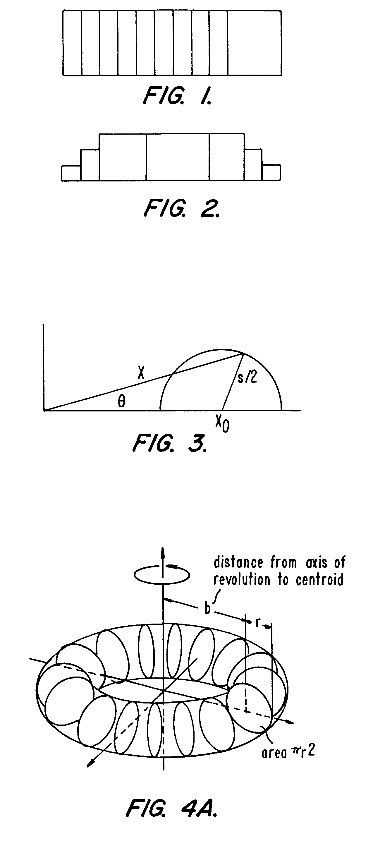
[0051]As an introductory example, a simple square spot with a treatment intensity of approximately 0.25 μm per pulse is used. The overlap is set to 33%. A 1 mm square spot centered at position (in mm) [0, 0] will have the next spot at [0, 0.33]. The area the two pulses have in common is 0.67 mm2. The offset (step size) from the first pulse is 0.33 mm. Continuing this sequence for a total of N pulses will produce a treated path of width 1 mm, and length 0.33*N mm. The overlap is 33% so the last pulse to coincide with the first pulse is the third pulse. The fourth pulse's edge is immediately adjacent to the first pulse. Assuming that the positioning is perfect, they will share a common edge. Looking in from a mer...


PUM


Abstract

Scanning spot locations are generated for ablating tissue using a scanning laser beam over a treatment region by taking a target function representing a desired lens profile of ablation with a basis function representing a treatment profile produced by overlapping scanning spots in a particular treatment pattern. In some embodiments, the basis function is a two-dimensional function representing a two-dimensional section of a three-dimensional treatment profile, which has symmetry with respect to the two-dimensional section extending along the treatment pattern. For example, the treatment pattern is generally straight for myopic and hyperopic cylinders, and is generally circular for myopia and hyperopia. The fit produces ablation depths for discrete scanning spots, which are used to calculate the number of pulses at each reference position along the two-dimensional section. The pulses are distributed along the treatment pattern to produce the desired overlapping effect.

Description

[0001]This application is a divisional of U.S. patent application Ser. No. 09 / 805,737, filed Mar. 13, 2001 now U.S. Pat. No. 6,673,062, which is based on and claims the benefit of U.S. Provisional Patent Application No. 60 / 189,633, filed Mar. 14, 2000, the entire disclosures of which are incorporated herein by reference.BACKGROUND OF THE INVENTION[0002]The present invention relates generally to tissue removal techniques and, more particularly, to generating locations for scanning with a laser to achieve a desired ablation profile for correction of errors in vision during laser eye surgery.[0003]A scanning system has the ability to trace out an arbitrary pattern with a small low energy spot. In most cases, a small spot equates to finer scanning details but at the expense of requiring more pulses to remove a given volume. The notion that a small spot will give a better fit than a large spot is generally true for arbitrary spot and ablation shapes, but the spot shapes can also affect t...

Claims


Application Information

Patent Timeline
Patent Type & Authority Patents(United States)
IPC IPC(8): A61B18/18A61B18/20A61F9/007A61F9/01
CPCA61F9/008A61F9/00804A61F2009/00897A61F2009/00882A61F2009/00872A61F2009/0088A61F2009/00844
Inventor YEE, KINGMANGROSS, ERIK
Owner AMO MFG USA INC
Why Eureka
Try Eureka